What is the Measurement in Floor Plans?
Floor plans are fundamental documents in architecture, interior design, real estate, and construction. They serve as scaled diagrams depicting the layout of a building or space from a bird's-eye view. A crucial aspect of understanding and utilizing floor plans effectively lies in comprehending the measurements they convey. These measurements dictate the size and dimensions of rooms, walls, openings, and other architectural features, providing a vital foundation for planning, design, and execution.
The measurements presented on a floor plan are not merely arbitrary numbers; they represent the real-world dimensions of the intended space. Accuracy in these measurements is paramount, as even minor discrepancies can lead to significant problems during construction or renovation. Errors in floor plan measurements can result in miscalculations in material quantities, furniture placement difficulties, and even structural issues. Therefore, understanding the conventions and methods used to represent measurements on floor plans is crucial for professionals and homeowners alike.
This article delves into the intricacies of measurements in floor plans, covering the units of measurement, the types of dimensions typically included, the methods of displaying those dimensions, and the implications of accuracy. It aims to provide a comprehensive understanding of how to interpret and utilize floor plan measurements effectively.
Units of Measurement Used in Floor Plans
The unit of measurement used in a floor plan is a fundamental aspect that dictates how dimensions are interpreted. The choice of unit is often dependent on geographical location, industry standards, and the scale of the project. While metric and imperial systems are both prevalent, specific conventions are typically adhered to within certain regions.
In the United States, the imperial system, particularly feet and inches, is the standard unit of measurement for floor plans. Dimensions are typically represented in feet and inches, with inches being indicated by a double quotation mark (") and feet indicated by a single quotation mark ('). For example, a dimension of ten feet and six inches would be written as 10' 6". In some cases, particularly for smaller dimensions, measurements may be expressed solely in inches. Decimals are commonly used to represent fractional inches, such as 10' 6.5".
In most other parts of the world, the metric system is the standard for floor plans. The primary unit of measurement within the metric system is the meter (m). However, for most architectural applications, millimeters (mm) are the preferred unit due to the greater precision they offer. Dimensions are usually expressed in millimeters without any unit symbol. For example, a dimension of three meters would be represented as 3000. Decimal millimeters are generally avoided in architectural drawings, opting instead for whole numbers.
Understanding the units of measurement used in a particular floor plan is critical for correctly interpreting the dimensions. Failure to recognize the unit can lead to drastically incorrect estimations and subsequent errors in the building process. Therefore, it is essential to always check the drawing title block or a designated notes section, where the units of measurement are invariably specified. It is also prudent to be aware of the conventions within the relevant region or industry.
Types of Dimensions Included in Floor Plans
Floor plans typically include a range of dimensions that provide a comprehensive overview of the space's layout and size. These dimensions can be broadly categorized as overall dimensions, interior dimensions, and feature-specific dimensions, each serving a distinct purpose in understanding the spatial arrangement.
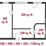
Overall dimensions denote the total length and width of the building or space. These measurements are usually placed on the exterior of the plan and indicate the maximum extent of the structure. They are crucial for determining the building's footprint, ensuring it fits within property boundaries, and calculating overall square footage. Overall dimensions provide the broadest understanding of the building's size and are often the first dimensions consulted when reviewing a floor plan.
Interior dimensions specify the size of individual rooms, hallways, and other interior spaces. These dimensions are placed within the floor plan to indicate the length, width, and height of each room. They are crucial for determining furniture placement, space planning, and ensuring compliance with building codes regarding room sizes. Interior dimensions often include measurements between walls, door openings, and window placements, allowing for detailed spatial analysis.
Feature-specific dimensions provide the size and location of specific architectural elements, such as doors, windows, stairs, and built-in features like fireplaces or cabinets. These dimensions are vital for ensuring proper installation and functionality of these elements. For example, the dimensions of a door dictate the size of the opening required in the wall, while the dimensions of a window determine the amount of natural light that will enter the room. Stair dimensions include the rise and run of steps, ensuring comfortable and safe usage. These feature-specific dimensions are often presented as callouts with arrows pointing to the relevant feature on the plan.
In addition to these categories, floor plans may also include dimensions related to wall thicknesses, column placements, and other structural elements. These dimensions are particularly important for structural engineers and contractors who need to ensure the stability and integrity of the building. Understanding all these types of dimensions is crucial for a comprehensive understanding of the floor plan and its implications for the building process.
Methods of Displaying Dimensions on Floor Plans
The way dimensions are displayed on floor plans is crucial for clarity and accuracy. Standard conventions ensure that measurements are easily understood and reduce the potential for misinterpretation. These conventions involve the use of dimension lines, extension lines, and dimension text, each serving a specific role in conveying the measurement information.
Dimension lines are thin, solid lines that indicate the distance being measured. They are typically drawn parallel to the feature being dimensioned and extend slightly beyond the extension lines. The dimension line has arrowheads at each end, pointing to the extension lines. The distance between the arrowheads is the dimension being represented. These lines are a key visual element in conveying measurements.
Extension lines, also known as witness lines, extend from the feature being measured to the dimension line. They are also thin, solid lines that are perpendicular to the dimension line. Extension lines do not touch the feature being measured but start slightly away from it to avoid confusion with the architectural lines of the plan. They provide a visual connection between the feature and the dimension, ensuring that the measurement is clearly associated with the correct element.
Dimension text provides the numerical value of the measurement. It is typically placed above the dimension line, centered between the extension lines. The text should be clear, legible, and in a consistent font size that is easily readable. The units of measurement are usually omitted from the dimension text if they are specified elsewhere on the drawing. However, if there are mixed units, the appropriate unit symbols (e.g., ' for feet, " for inches) are included alongside the numerical value. Sometimes, the dimension text is placed below the dimension line, especially if there is limited space above it.
In addition to these basic elements, floor plans may also use continuous dimensioning, where a series of dimensions are chained together to show the overall length of a series of spaces or features. This method can be useful for showing the relationship between different rooms or components within a building. Overall dimensions are usually placed outside the structure, indicating the total length and width. Smaller dimensions are placed inside to indicate the sizes of individual rooms.
Effective use of these conventions ensures that the dimensions on a floor plan are clear, accurate, and easily understood. Adherence to these standards is crucial for minimizing errors and ensuring the success of the design and construction process.
Implications of Accuracy in Floor Plan Measurements
Accuracy in floor plan measurements is not merely a matter of precision; it has significant implications for the entire design and construction process. Inaccurate measurements can lead to a cascade of problems, impacting everything from material procurement to structural integrity. Therefore, ensuring the accuracy of measurements is critical for minimizing errors, controlling costs, and achieving a successful outcome.
One of the most immediate implications of inaccurate floor plan measurements is the potential for errors in material quantities. If the dimensions of rooms or walls are incorrect, the calculations for the amount of flooring, drywall, paint, or other materials needed for the project will be inaccurate. This can lead to either over-ordering materials, resulting in wasted resources and increased costs, or under-ordering materials, causing delays and requiring additional procurement efforts. Accurate floor plan measurements are essential for precise material estimation, which is a critical factor in budgeting and project management.
Inaccurate measurements can also lead to problems during the construction phase. If the dimensions of rooms are incorrect, furniture may not fit as planned, or there may be insufficient space for appliances or fixtures. This can result in costly rework, delays, and compromises in the design. Additionally, inaccurate wall dimensions can affect the placement of doors and windows, potentially impacting the overall functionality and aesthetics of the space. Accurate floor plans serve as a blueprint for construction, and their accuracy is essential for ensuring that the final product aligns with the intended design.
Furthermore, inaccurate floor plan measurements can have structural implications, especially in complex building designs. Incorrect dimensions can lead to miscalculations in load-bearing capacity, potentially compromising the stability and safety of the building. This is particularly critical in the design of structural elements such as beams, columns, and foundations. Accurate floor plans provide the basis for structural analysis and engineering calculations, ensuring that the building is structurally sound and meets all relevant building codes and regulations.
To ensure accuracy in floor plan measurements, it is crucial to use precise measuring tools, such as laser distance measurers or high-quality measuring tapes. It is also important to verify all measurements and dimensions multiple times to minimize the potential for errors. In addition, utilizing computer-aided design (CAD) software can help ensure accuracy by providing precise drawing tools and automated dimensioning capabilities. Regular quality control checks throughout the design and construction process are also essential for identifying and correcting any errors early on.

Overview Measurements On Floor Plans Roomsketcher Help Center

12 Examples Of Floor Plans With Dimensions

How To Properly Read Floor Plans And What Details Look For

Overview Measurements On Floor Plans Roomsketcher Help Center

Floor Plans With Dimensions Including Examples Cedreo

Overview Measurements On Floor Plans Roomsketcher Help Center

How To Read A Floor Plan With Dimensions Houseplans Blog Com

Overview Measurements On Floor Plans Roomsketcher Help Center

How To Read A Floor Plan With Dimensions Houseplans Blog Com

Add Measurements
Related Posts