Simple 2D Plan Drawing With Dimensions: A Comprehensive Guide
Creating a 2D plan drawing is a fundamental skill for architects, engineers, interior designers, and anyone involved in construction or spatial planning. A 2D plan, also known as a floor plan, represents a building or space as seen from above, offering a bird's-eye view of the layout. This type of drawing is essential for visualizing and communicating spatial relationships, identifying potential design issues, and providing a clear guide for construction. The addition of accurate dimensions transforms a simple sketch into a precise and usable document.
This article focuses on the principles and practices of creating simple 2D plan drawings with dimensions. It will cover the essential elements of a 2D plan, methods for accurate measurement and dimensioning, best practices for clarity and readability, and common software tools used for creating these drawings. The goal is to provide a comprehensive understanding of how to develop accurate and effective 2D plans that can be used for a variety of purposes.
Understanding the Essential Elements of a 2D Plan
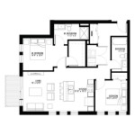
A well-structured 2D plan incorporates several key elements working together to convey information effectively. These elements include walls, doors, windows, furniture, fixtures, and annotations. Each element must be represented accurately and consistently according to accepted drafting conventions.
Walls are the primary structural component of any building or space and are typically depicted as thick, solid lines. The thickness of the lines helps distinguish walls from other elements and clarifies their structural importance. Interior walls might be represented with slightly thinner lines compared to exterior walls. Different types of walls, such as load-bearing walls, fire-rated walls, or partition walls, can be represented with distinct line styles or hatching patterns to convey specific information.
Doors are represented as an opening in the wall, along with an arc indicating the direction of the door swing. This is crucial for understanding the flow of movement within the space and ensuring that doors do not obstruct passageways or furniture placement. The door swing should be accurately depicted based on the actual hand and orientation of the door. Different types of doors, such as sliding doors, bi-fold doors, or pocket doors, should be represented accordingly.
Windows are typically shown as openings in the wall with two or three parallel lines indicating the window frame and glazing. The size and placement of windows are critical for understanding the natural light and ventilation within the space. Different types of windows, such as casement windows, awning windows, or sliding windows, can be represented with distinct symbols or annotations.
Furniture and fixtures, such as tables, chairs, beds, kitchen appliances, and bathroom fixtures, provide context and scale to the plan. These elements are typically drawn to scale and placed in their intended locations to demonstrate how the space will be used. While the level of detail can vary depending on the purpose of the drawing, it's important to represent the overall size and shape of these elements accurately. Furthermore, showing the placement of electrical outlets and plumbing connections can be beneficial.
Annotations, including room names, dimensions, notes, and symbols, provide additional information and clarity to the plan. Room names help identify the function of each space, while dimensions provide precise measurements for construction and layout. Notes can be used to clarify specific design details or material specifications. Symbols, such as north arrows or electrical symbols, provide standardized information that is universally understood.
Methods for Accurate Measurement and Dimensioning
Accurate measurement and dimensioning are paramount in creating a usable 2D plan. The dimensions provide the precise measurements required for construction, layout, and material estimation. Inaccurate dimensions can lead to costly errors and delays in the project.
Before starting the drawing, it's essential to establish a consistent scale. This scale dictates the relationship between the drawing and the actual size of the space. Common scales include 1/4 inch = 1 foot or 1/8 inch = 1 foot. Choosing an appropriate scale depends on the size of the space being represented and the level of detail required. Once the scale is established, it should be maintained throughout the entire drawing.
There are several methods for obtaining accurate measurements of existing spaces. Laser measuring tools offer the highest level of accuracy and efficiency. These tools can measure distances, areas, and volumes with minimal error. Tape measures are another common tool, but they require careful handling to avoid inaccuracies. It's important to use a high-quality tape measure and to ensure that it is held straight and taut during measurements. Surveying equipment may be necessary for larger or more complex spaces.
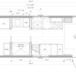
Dimensioning involves adding measurements to the drawing to indicate the size and location of various elements. Dimensions should be clear, concise, and easy to read. There are two main types of dimensioning: overall dimensions and detail dimensions. Overall dimensions indicate the total length and width of the space, while detail dimensions indicate the size and location of individual elements, such as walls, doors, windows, and fixtures.
Dimensions are typically represented with extension lines, dimension lines, and dimension text. Extension lines extend from the object being measured to the dimension line. The dimension line indicates the distance being measured, and the dimension text provides the numerical value of the measurement. The dimension text should be placed above or below the dimension line and should be clearly legible. It is important to use consistent units of measurement, such as feet and inches, and to indicate the units clearly.
When dimensioning a plan, it's important to follow a logical order. Start with the overall dimensions of the space and then work down to the detail dimensions. Place dimensions outside the object being measured to avoid cluttering the drawing. Avoid overlapping dimension lines or extension lines. Use leader lines to point to specific features or elements when necessary. It is also crucial to double-check all dimensions for accuracy before finalizing the drawing.
Best Practices for Clarity and Readability
Clarity and readability are crucial aspects of a 2D plan drawing. A clear and readable plan is easy to understand and interpret, minimizing the potential for errors and miscommunication. There are several best practices that can be followed to enhance the clarity and readability of a 2D plan.
Line weights play a significant role in distinguishing different elements in the drawing. Use thicker lines for walls and structural elements and thinner lines for furniture, fixtures, and annotations. Varying the line weights helps create a hierarchy of information and makes the drawing easier to visually parse. Consistent line weights are also crucial for maintaining a professional look and feel.
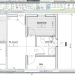
Layering is an important technique for organizing and managing the elements in a 2D plan. By placing different elements on separate layers, it becomes easier to control their visibility, edit their properties, and manage their relationships. For example, walls can be placed on one layer, furniture on another, and dimensions on a third. This allows for selective editing and printing of specific elements without affecting the rest of the drawing.
Text and annotation should be clear, concise, and easy to read. Use a consistent font and font size throughout the drawing. Avoid using overly decorative or complex fonts that can be difficult to decipher. Place text horizontally whenever possible to improve readability. Use leader lines to connect text to specific features or elements. Proofread all text carefully to ensure accuracy and avoid spelling errors.
Symbols and conventions should be used consistently throughout the drawing. Use standard architectural symbols for doors, windows, electrical outlets, and plumbing fixtures. Adhere to accepted drafting conventions for representing different types of walls, floors, and ceilings. Consistency in the use of symbols and conventions ensures that the drawing is universally understood.
Whitespace, or negative space, is an important element in creating a clear and readable plan. Avoid crowding the drawing with too many elements. Leave sufficient space between objects and annotations to allow the eye to easily distinguish between them. Whitespace helps to create a sense of balance and visual hierarchy in the drawing.
It's always a good practice to review and revise the drawing multiple times before finalizing it. Check for errors in dimensions, inconsistencies in symbols, and areas where the drawing could be made clearer or more readable. Consider having someone else review the drawing to provide a fresh perspective and identify any potential issues.

Create Professional 2d Floor Plans Roomsketcher

Create Professional 2d Floor Plans Roomsketcher

2d Floor Plans Plan Design Home Small Kitchen

2d Drawing Gallery Floor Plans House

Draw 2d Floor Plans In Minutes Not Hours Cedreo

Beautiful 2d Floor Plan Ideas Engineering Discoveries Home Map Design Building House Plans Designs

House Plan Drawing Samples 2d Drawings

Create Professional 2d Floor Plans Roomsketcher

2d Plan Of The Existing First Floor Building All Dimensions Are In M Scientific Diagram

Create Professional 2d Floor Plans Roomsketcher
Related Posts