How To Create a Floor Plan in 3ds Max
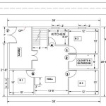
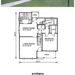
3ds Max, a powerful 3D modeling and rendering software, isn't solely limited to creating complex visualizations and animations. It can also be effectively used for architectural design, including the creation of accurate and detailed floor plans. While dedicated CAD software might seem the obvious choice, 3ds Max offers flexibility in incorporating 3D elements and visualizations directly within the floor plan, providing a more comprehensive design representation. This article outlines a step-by-step process for creating floor plans in 3ds Max.
Before beginning, it's essential to understand the fundamental principles of creating architectural drawings. Accuracy and attention to detail are paramount. A well-constructed floor plan serves as the foundation for all subsequent design and visualization processes. It is crucial to use accurate measurements, consistent units, and maintain proper layering for efficient workflow and modification.
1. Setting Up the Project and Units
The first step involves configuring the 3ds Max environment for architectural modeling. This primarily involves setting up the appropriate units and grid settings. Incorrect unit settings can lead to scaling issues and inaccuracies that propagate throughout the entire project. The units should correspond to the real-world dimensions of the building being modeled.
To configure units, navigate to the "Customize" menu and select "Units Setup." In the "Units Setup" dialog box, choose the desired unit system. For architectural projects using the metric system, "Metric" should be selected, and the preferred unit, such as "Meters" or "Centimeters," should be chosen from the dropdown menu. For projects using the imperial system, select "US Standard" or "Generic Units," and specify the appropriate unit, such as "Feet" or "Inches."
After setting the unit system, it's crucial to adjust the "System Unit Setup." This setting determines how 3ds Max internally interprets measurement values. It's critical that the "System Unit Scale" matches the display unit selected earlier to avoid potential discrepancies. If the display unit is set to "Meters," then the System Unit Scale should also be set to "1 Unit = 1.0 Meters."
Next, configure the grid settings to facilitate accurate placement of objects. Access the grid settings by right-clicking on the grid icon located at the bottom of the 3ds Max interface. This opens the "Grid and Snap Settings" dialog box. In the "Home Grid" tab, adjust the "Grid Spacing" to a value that's suitable for the scale of the project. For example, if working in meters, a grid spacing of 0.1 (10 centimeters) can be used. The "Major Line Every Nth Grid Line" setting determines the frequency of major grid lines, which can help visualize larger increments. For projects using the imperial system, the grid spacing should be set accordingly.
Consider also adjusting the "Snap Settings" to ensure precise object placement. By enabling snapping, objects can be easily aligned to grid points, vertices, edges, or other geometric features. Access the "Snaps" tab in the "Grid and Snap Settings" dialog box. Select the relevant snapping modes, such as "Vertex," "Midpoint," "Edge," and "Grid Points," based on the modeling requirements. The snap strength can also be adjusted to fine-tune the snapping behavior.
2. Importing or Drawing the Floor Plan Outline
With the project environment properly configured, the next step is to import or draw the floor plan outline. If a pre-existing floor plan drawing is available in a compatible format, such as DWG or DXF, it can be imported directly into 3ds Max. If no existing drawing is available, or if the existing drawing is not suitable, the floor plan outline can be drawn manually within 3ds Max using spline tools.
To import a floor plan drawing, navigate to the "File" menu and select "Import." Choose the appropriate DWG or DXF file and configure the import settings. Pay close attention to the "Units" setting during import. Ensure that the imported drawing's units match the units set in 3ds Max to avoid scaling issues. The "Rescale" option can be used to convert the drawing to the correct units if necessary.
Alternatively, the floor plan outline can be drawn manually using spline tools. Spline tools are found in the "Create" panel under the "Shapes" category. The "Line" tool is the most commonly used spline tool for creating floor plan outlines. By clicking and dragging in the viewport, individual line segments can be created. Pressing "Shift" while drawing ensures that the line segments are perfectly horizontal or vertical.
To create curved walls or features, use the "Arc" or "Bezier" spline tools. These tools allow for the creation of smooth, curved lines. Experiment with different spline tools and settings to achieve the desired shapes. When drawing the floor plan outline, it's essential to maintain accuracy and consistency. Use the snap settings to ensure that lines are properly aligned and connected. Pay close attention to the dimensions of walls, doors, and windows.
Once the floor plan outline is drawn, the individual spline segments can be joined together to create a closed shape. Select all the spline segments and attach them using the "Attach" button in the "Modify" panel. After attaching, use the "Weld" vertex operation to ensure that the endpoints of the spline segments are properly connected. Select all the vertices and increase the "Threshold" value until the vertices are welded together. This creates a single, continuous spline that represents the floor plan outline.
3. Creating Walls and Openings
After establishing the floor plan outline, the next crucial step is to create the walls and openings such as doors and windows. 3ds Max offers several methods for generating walls from splines, each with its own advantages. One common approach involves using the "Extrude" modifier.
Select the closed spline representing the floor plan outline. In the "Modify" panel, apply the "Extrude" modifier. The "Amount" parameter in the Extrude modifier determines the height of the walls. Enter the desired wall height value, ensuring it corresponds to the intended ceiling height. For example, for a standard ceiling height of 2.7 meters, enter 2.7 as the "Amount" value.
To create openings for doors and windows, various techniques can be employed. One method is to create separate splines representing the door and window openings. Position these splines on the floor plan where the openings are desired. Then, use the "Boolean" compound object to subtract the openings from the wall geometry. Select the wall object and go to the "Create" panel, choose "Compound Objects," and then select "Boolean." Choose "Subtraction" as the operation type and select the spline representing the door or window opening to subtract it from the wall.
Alternatively, the "ProBoolean" compound object can be used. It offers more advanced options and greater control over the Boolean operation. In particular, it allows for creating more complex openings and maintaining the wall's parametric properties, which can be useful for future modifications. The process is similar to using the "Boolean" object, but with a wider range of options available.
Another method for creating openings involves using the "Editable Poly" modifier. Convert the wall object to an "Editable Poly" object. Then, select the faces where the door and window openings are to be created. In the "Polygon" sub-object level, use the "Inset" function to create an inner boundary representing the frame of the opening. Then, delete the selected faces to create the opening.
For creating doors and windows, either model them from scratch or import existing 3D models. Place them in the openings created earlier. Ensure that the doors and windows are properly scaled and aligned with the openings. Use the snap settings to ensure accurate placement. Consider creating separate layers for walls, doors, and windows to improve organization and visibility.
4. Adding Interior Details and Furniture
Once the walls and openings are established, the next step involves adding interior details and furniture to the floor plan. This includes elements such as flooring, ceilings, fixtures, and furniture. These details enhance the visual representation of the floor plan and provide a more realistic sense of the space.
To create flooring, create a plane object that covers the entire floor area. Position the plane slightly below the bottom of the walls to avoid Z-fighting (where two surfaces occupy the same space, causing flickering). Apply a material to the plane representing the desired flooring material, such as wood, tile, or carpet. Adjust the material settings, such as color, texture, and reflection, to achieve the desired look.
To create ceilings, similar to the flooring, create a plane object that covers the entire ceiling area. Position the plane at the top of the walls. Apply a material to the plane representing the desired ceiling material, such as drywall or suspended ceiling tiles. Consider adding details such as recessed lighting or ceiling fans to enhance the realism.
Import or create 3D models of furniture and fixtures. A large selection of pre-made 3D models of furniture, fixtures, and appliances can be downloaded from online resources. Alternatively, the required models can be built from scratch using primitive shapes and modeling tools within 3ds Max.
Position the furniture and fixtures within the floor plan according to the design intent. Use the snap settings to ensure accurate placement. Pay attention to the scale and proportion of the furniture relative to the room size. Avoid overcrowding the space with too much furniture.
Add details such as lighting fixtures, electrical outlets, and plumbing fixtures to further enhance the realism of the floor plan. These details provide a more complete and accurate representation of the building's systems.
Organize the objects in the scene using layers. Create separate layers for walls, doors, windows, furniture, fixtures, and other elements. This improves organization and allows for selectively hiding or showing elements to simplify the scene and improve performance. Use descriptive layer names to easily identify the contents of each layer.
Consistent naming conventions for the objects within the scene are also crucial. Names should clearly identify the object's function or type (e.g., "Wall_Exterior_North", "Door_Bedroom_01", "Sofa_LivingRoom"). This makes it easier to locate and manage objects within the scene.
By following these steps, a detailed and accurate floor plan can be created in 3ds Max. Remember that consistent practice is key to mastering these techniques. The flexibility that 3ds Max provides allows for a workflow that seamlessly blends architectural design and visualization.

3ds Max Tutorial 3d Cut Plan And Best Vray Setting

Create 3d Floor Plan Rendering In 3ds Max Architecture Tutorial

How To Make 3d Floor Plan 3ds Max Part I

How To Make 3d Floor Plan In 3ds Max Part 03

3d Floor Plan Designing With Photo And 3ds Max Part 01 House Design Houseplan

Your Project Virtually With 3ds Max Architectural Floor Plan Rendering Diseño De Casa Planos Para Construir Casas Modernas

Easy Steps How To Make 3d Floor Plan In 3ds Max Part 01

Tutorial 3ds Max How To Create Floor Plan Part 4

3ds Max Extruding A Floor Plan

3ds Max Pt 2 Extruding A Floor Plan Design Tutorials
Related Posts


