How to Create a 3D House Plan in AutoCAD
AutoCAD, a powerful computer-aided design (CAD) software, is widely used for creating precise 2D and 3D drawings. Developing a 3D house plan in AutoCAD allows for a comprehensive visualization of the structure before physical construction begins. This process encompasses several stages, from setting up the drawing environment to extruding 2D elements into 3D models. This article provides a detailed guide on the steps involved in creating a 3D house plan using AutoCAD.
Before beginning the 3D modeling process, it is paramount to ensure the AutoCAD environment is properly configured. This includes setting the units, establishing layers, and configuring the visual styles. Proper setup contributes significantly to the efficiency and accuracy of the subsequent modeling stages.
Setting Up the AutoCAD Environment
The initial step involves establishing the appropriate units for the drawing. To do this, the UNITS command should be invoked. This command allows selection of units such as millimeters, centimeters, meters, inches, or feet. Selecting the appropriate unit system is crucial for maintaining consistency and accuracy throughout the entire project. Furthermore, the precision level needs to be defined, specifying the number of decimal places to be displayed. This setting dictates the level of detail in the measurements.
Layers are essential for organizing different elements of the drawing. Using the LAYER command, distinct layers should be created for walls, doors, windows, furniture, and other architectural components. Assigning different colors and linetypes to each layer enhances visual clarity and simplifies object selection for editing. Implementing a well-organized layer structure is crucial for efficient model management and modification.
Visual styles control how the 3D model is displayed. The VISUALSTYLES command provides access to various visual styles such as 2D Wireframe, 3D Wireframe, Conceptual, Hidden, Realistic, and Shaded. The choice of visual style depends on the specific modeling task. For example, the 'Conceptual' or 'Realistic' style provides a better representation of the final appearance of the house, while the '2D Wireframe' or '3D Wireframe' styles are useful for precise editing and object selection.
Coordinate systems are equally important in setting up the environment. Ensure the World Coordinate System (WCS) is appropriately aligned, typically with the X and Y axes representing the horizontal plane and the Z-axis representing the vertical dimension. Understanding and manipulating the User Coordinate System (UCS) is also important, as it allows defining alternative coordinate systems for simplifying drawing in specific planes or at specific angles.
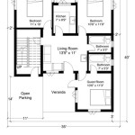
Creating the 2D Foundation Plan
The foundation of any 3D model lies in its 2D base. The 2D floor plan serves as the blueprint for the 3D structure. Accuracy at this stage is critical because any errors in the 2D plan will be propagated into the 3D model. Several AutoCAD commands are utilized in this process, including LINE, POLYLINE, OFFSET, and TRIM.
Begin by drawing the exterior walls of the house using the LINE or POLYLINE command. POLYLINE is often preferred as it creates a single, continuous object, simplifying selection and manipulation later. Accurate dimensions should be entered using direct distance entry or coordinate input. The THICKNESS property can be used at this stage to give the lines a width that represents the actual wall thickness, making it easier to visualize the wall layout.
Interior walls are created in a similar manner. Ensure that the walls are accurately positioned with respect to the exterior walls. The OFFSET command is very useful here, as it allows creating parallel lines at a specified distance. This is particularly helpful for creating walls with consistent thicknesses. The TRIM command is subsequently used to clean up any overlapping or intersecting lines, ensuring a clean and accurate 2D floor plan.
Doors and windows are essential architectural elements that need to be incorporated into the 2D floor plan. Represent these features as gaps in the walls, with appropriate dimensions to match the actual door and window sizes. Use the LINE and OFFSET commands to draw the openings, and the TRIM command to create the necessary gaps in the walls. Blocks can also be used to represent doors and windows, allowing for easy insertion and standardization of these elements.
Dimensions and annotations are essential for clarifying the design. The DIMENSION command is used to add accurate dimensions to the walls and openings. Text annotations can be added to label different areas of the house, such as 'Living Room', 'Bedroom', or 'Kitchen'. Using appropriate text styles and dimension styles ensures that the annotations are legible and consistent throughout the drawing.
Extruding 2D Elements into 3D
Once the 2D floor plan is complete and accurate, the next step involves converting it into a 3D model. This is primarily achieved using the EXTRUDE command. Extrusion involves giving height to the 2D objects, effectively turning them into 3D solids. Other relevant commands include UNION, SUBTRACT, and INTERSECT, which are used for combining or modifying the resulting 3D solids.
Select the wall polylines and use the EXTRUDE command to give them height. The extrusion height should correspond to the desired wall height of the house (e.g., 10 feet or 3 meters). Ensure that the extrusion direction is aligned with the Z-axis, which represents the vertical dimension. The resulting 3D solids will represent the walls of the house.
Use the SUBTRACT command to create openings for doors and windows. First, create 3D solids that represent the size and position of the door and window openings. Then, use the SUBTRACT command to subtract these solids from the wall solids. This will create the necessary openings in the walls for the doors and windows. This method ensures that the openings are precisely positioned and sized.
Create 3D models of doors and windows using similar techniques. These can be created from 2D profiles and extruded to the appropriate thickness. Alternatively, pre-made 3D blocks of doors and windows can be inserted into the model. These blocks can be downloaded from online libraries or created from scratch. Ensure that the doors and windows are accurately positioned within the openings.
The roof can be created using various methods, depending on the roof type. For a simple flat roof, the 2D outline of the house can be extruded upwards to create a solid roof slab. For more complex roof shapes, such as pitched roofs, cones, or pyramids may be used and manipulated to achieve the desired roof geometry. The UNION command can be used to combine different roof elements into a single solid.
Adding details such as floors, ceilings, and interior features enhances the realism of the 3D model. Floors can be created by extruding the floor outline downwards by a small amount. Ceilings can be created similarly, by extruding the ceiling outline upwards. Interior features such as furniture can be either modeled from scratch or imported as 3D blocks. Carefully positioning these features adds significant detail and realism to the model.
Finally, applying materials and textures enhances the visual appeal of the model. The MATERIALS command allows assigning various materials to the different 3D objects. Choose materials that realistically represent the actual building materials, such as brick, wood, concrete, or glass. Adjusting the material properties, such as color, reflectivity, and texture, further enhances the realism of the model. Render the model to create a realistic image of the house, which can be used for presentations or visualization purposes. The RENDER command allows for creating high-quality images of the 3D model with realistic lighting and shadows.

Autocad 2d To 3d House Modeling Simple Floor Plan 2024

Create 3d House Using Autocad In Easy Steps 1

Autocad 3d House Modeling Tutorial 1

Floor Plan Create 2d 3d Plans Autodesk

Autocad 3d House Modeling Tutorial 1

Autocad 2d Plans And 3d House Modeling Tutorials

Create A Building In 3d Autocad Tutorial And S

Create A Building In 3d Autocad Tutorial And S

Autocad 3d House Design

3d Autocad House Building Design Free Dwg File
Related Posts