How To Create a 3D Floor Plan in AutoCAD
AutoCAD, a widely recognized computer-aided design (CAD) software, offers extensive capabilities for creating both 2D and 3D architectural designs. Generating a 3D floor plan within AutoCAD allows for a more comprehensive visualization of the spatial layout, design elements, and overall aesthetic appeal of a building or interior space. This article provides a structured approach to constructing a 3D floor plan using AutoCAD, outlining essential steps and techniques to facilitate a detailed and accurate representation.
Before initiating the 3D modeling process, ensure that the AutoCAD workspace is configured appropriately. This involves setting the units of measurement (e.g., meters, feet, inches) to match the intended scale of the floor plan. Access the "Units" command (typing "UNITS" in the command line) and specify the desired unit type and precision. Furthermore, selecting an appropriate 3D modeling workspace is crucial. AutoCAD typically offers "3D Modeling" and "3D Basics" workspaces, each tailored to different levels of complexity. The "3D Modeling" workspace provides a more comprehensive set of tools and features for advanced 3D design.
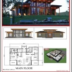
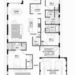
The foundation of any 3D floor plan lies in its 2D representation. Accurate and precise 2D drawings serve as the basis for the subsequent 3D modeling stages. Start by importing or drawing the 2D floor plan layout within AutoCAD. This layout should include all essential architectural elements such as walls, doors, windows, and any built-in features like cabinets or staircases. Utilize AutoCAD's precision drawing tools, including "Line," "Polyline," "Offset," and "Trim," to ensure accurate dimensions and clean connections between elements. It is advisable to create separate layers for different categories of objects (e.g., walls, doors, windows) to facilitate organization and ease of editing later in the process.
Establishing the 2D Foundation
The 2D floor plan serves as the blueprint for the 3D model. Precision in this initial stage is paramount to avoid compounding errors later. When drawing walls, ensure they are accurately represented in terms of thickness and alignment. Use the "Offset" command to create parallel lines representing the inner and outer faces of the walls, and then use the "Trim" command to clean up intersections and create closed polylines. For doors and windows, represent their openings within the walls using appropriate dimensions. Consider using dynamic blocks for doors and windows, as these blocks can be easily adjusted and modified as the design evolves. Consistent use of layers for different elements allows for selective visibility and manipulation, streamlining the modeling process.
Once the 2D floor plan is complete, transition to the 3D modeling environment. This involves changing the view to a 3D perspective, typically using the "SW Isometric" view or similar. The next step is to extrude the 2D elements vertically to create 3D solids. The "Extrude" command is used to give thickness or height to 2D shapes. For walls, extrude the polylines representing the wall outlines to a height that corresponds to the ceiling height of the floor plan. Ensure that all walls are extruded to the same height for consistency. Similarly, extrude other elements such as columns or structural supports to their appropriate heights.
Creating openings for doors and windows requires a slightly different approach. First, extrude the door and window openings in the walls to the same height as the walls. Then, create 3D solids representing the doors and windows themselves. These can be created using basic 3D shapes like boxes or custom-designed using more advanced modeling techniques. Position the doors and windows within their respective openings, ensuring they fit precisely. Use the "Subtract" command to create the openings in the walls. This command subtracts one solid from another, effectively creating the door and window openings within the solid wall.
The process of subtracting solids is critical for defining the architectural features of the floor plan. After positioning the 3D representation of the door in the designated opening, the "Subtract" command allows you to remove the volume occupied by the door from the volume of the wall. The same principle applies to windows. Accurate placement before subtraction is vital to ensure the openings are correctly aligned. After subtraction, the architectural openings become part of the 3D model, leading to a more realistic representation.
Elevating 2D Elements Into 3D Solids
The key to transforming a 2D floor plan into a 3D model lies in the "Extrude" command. By selecting a 2D object and specifying an extrusion height, you can generate a 3D solid object. For example, to create walls, extrude the 2D wall polylines to the desired ceiling height. Similarly, columns can be extruded from their 2D representations. Accurately defining the extrusion height for each element is crucial to maintain the correct proportions of the 3D model. For elements like doors and windows, it's often beneficial to create them as separate 3D models and then insert them into the wall openings.
The roof is an essential component of a 3D floor plan, contributing significantly to its overall aesthetic and visual appeal. The method for creating a roof depends on the roof's design. For a simple flat roof, extrude the outline of the building footprint vertically. For more complex roof shapes, such as pitched or gabled roofs, use AutoCAD's 3D modeling tools to create the desired geometry. The "Loft" command can be useful for creating curved or complex roof shapes by sweeping a profile along a specified path. Ensure that the roof overhangs the walls appropriately to provide realistic protection from the elements. Consider adding details such as gutters and downspouts for enhanced realism.
Interior elements such as furniture, fixtures, and appliances contribute significantly to the realism and functionality of a 3D floor plan. AutoCAD offers a library of pre-designed 3D models that can be imported and placed within the floor plan. Alternatively, these elements can be custom-designed using AutoCAD's 3D modeling tools. Pay attention to the scale and proportions of these elements to ensure they fit appropriately within the space. Arrange the furniture and fixtures in a logical and functional manner, considering factors such as circulation paths and accessibility. Adding interior elements helps to visualize how the space will be used and occupied.
Adding Detail and Realism
The inclusion of furniture, fixtures, and appliances elevates a basic 3D floor plan to a more realistic and usable design tool. Utilize AutoCAD's library of 3D models or create custom models to populate the interior spaces. When adding these elements, consider their scale and placement. Ensure that furniture is appropriately sized for the rooms and that circulation paths remain unobstructed. Arrange furniture to create functional living spaces, such as seating areas in living rooms and dining sets in dining rooms. Fixtures, such as lighting and plumbing, should be added to their appropriate locations, further enhancing the realism of the floor plan. The careful selection and placement of these elements allows for a more comprehensive understanding of the space and its potential uses.
Surface materials and textures play a crucial role in enhancing the visual appeal and realism of a 3D floor plan. AutoCAD allows you to apply different materials and textures to the surfaces of 3D objects. Use the "Materials" palette to access AutoCAD's library of pre-defined materials, or create custom materials using images and texture maps. Apply appropriate materials to walls, floors, ceilings, and furniture to simulate the appearance of real-world surfaces. For example, apply brick or stone textures to exterior walls, wood textures to floors, and fabric textures to furniture. Experiment with different materials and textures to achieve the desired aesthetic effect. Lighting can also significantly impact the appearance of materials and textures. Use AutoCAD's lighting tools to add artificial light sources to the scene and adjust their intensity and color to create realistic lighting effects.
Rendering is the final step in creating a visually compelling 3D floor plan. AutoCAD's rendering engine allows you to generate realistic images and animations of the 3D model. Customize rendering settings such as resolution, lighting, and shadows to achieve the desired level of detail and realism. Experiment with different rendering styles, such as photorealistic or artistic, to create different visual effects. Use the "Render" command to generate a high-quality image of the 3D floor plan. Post-processing software, such as Adobe Photoshop, can be used to further enhance the rendered image by adjusting colors, contrast, and sharpness. Presenting a well-rendered 3D floor plan is a valuable tool for communicating design ideas to clients and stakeholders.
By following these steps and utilizing AutoCAD's extensive 3D modeling tools, a detailed and accurate 3D floor plan can be created. Careful planning, precise execution, and attention to detail are key to producing a visually compelling and informative representation of the architectural design.

Floor Plan Create 2d 3d Plans Autodesk

Autocad 2d To 3d House Modeling Simple Floor Plan 2024

Autocad 3d Basics Tutorial To Model A Floor Plan Fast And Effective Part 1

Autocad 3d How To Draw A House Plan Fast And Easy

Create 3d House Floor Plan And Render In Autocad By Mahjabeen Sidd Fiverr

Autocad 2d Plans And 3d House Modeling Tutorials

Autocad 3d House Design Part 2 2d Plan To Conversion 2024

2d 3d Architecture House Floor Plan Design In Autocad Upwork

Create 3d House Using Autocad In Easy Steps 1

Design And Render 2d Floor Plan 3d Using Autocad Sketchup By Vbuildcon Fiverr
Related Posts

