How to Draw a House Plan in AutoCAD
AutoCAD, a leading computer-aided design (CAD) software, is widely used by architects, engineers, and designers to create precise 2D and 3D drawings. Crafting a house plan in AutoCAD requires a systematic approach, understanding of architectural conventions, and familiarity with the software's tools. This article outlines the steps involved in drawing a basic house plan in AutoCAD, providing a comprehensive guide for users of all skill levels.
Setting Up AutoCAD for Architectural Drawing
Before initiating the drawing process, it is crucial to configure AutoCAD to optimize the workspace for architectural design. This involves setting up the units, limits, and layers, which will enhance accuracy and organization throughout the project.
First, establish the drawing units. Type "UNITS" in the command line and press Enter. In the Drawing Units dialog box, select the desired unit of measurement, typically architectural units (feet and inches) for house plans. Set the precision to a suitable level, such as 1/16 of an inch, to ensure detailed representation. This selection will affect how AutoCAD interprets and displays measurements throughout the drawing process.
Next, define the drawing limits. Type "LIMITS" in the command line and press Enter. Specify the lower-left corner of the drawing area, usually (0,0). Then, specify the upper-right corner. The values you use here determine the overall size of your drawing area. Estimate the approximate dimensions of the house and add some buffer space around it. These limits will act as a visual boundary for the drawing space.
Creating and managing layers is essential for organizing different elements of the house plan, such as walls, doors, windows, and furniture. Layers allow you to control the visibility, color, linetype, and lineweight of individual objects. To create layers, type "LAYER" in the command line and press Enter. In the Layer Properties Manager, create new layers for each category of elements. Assign distinct colors and linetypes to each layer to visually differentiate them. For example, walls could be represented with a thick, solid red line on a dedicated "Walls" layer, while windows and doors could have their own layers with different colors and linetypes. Utilizing layers effectively simplifies the selection, modification, and overall management of the drawing.
Drawing the Basic Floor Plan
With AutoCAD properly configured, the next step is to begin drawing the floor plan. This involves creating the exterior walls, interior walls, and defining the layout of rooms and spaces within the house.
Start by drawing the exterior walls using the "Line" command (type "L" and press Enter). Refer to the architectural sketch or design specifications for the exact dimensions and layout. Click to specify the starting point of the first wall, and then enter the length and angle (or direction) of the wall. Ensure the "Ortho" mode (F8) is enabled to draw straight lines horizontally or vertically. Continue drawing the lines to form the perimeter of the house. Pay close attention to the accuracy of the dimensions, as these walls will form the foundation of the entire plan.
After drawing the exterior walls, create the interior walls using the same "Line" command. Refer to the design specifications to determine the placement and thickness of interior walls. Offset command (type "O" and press Enter) can be very useful for creating parallel lines. Specify the offset distance, usually the wall thickness, and select the existing wall to create a parallel line representing the opposite side of the wall. Ensure alignment and proper connection between interior and exterior walls. Use the "Trim" command (type "TR" and press Enter, then press Enter again to select all objects as cutting edges) to remove any overlapping lines and create clean intersections.
The “Offset” command is particularly useful when creating walls according to a specified thickness. The “Trim” command ensures only the necessary line segments remain creating a tidy drawing. By systematically drawing the exterior and interior walls, a basic floor plan is established.
Adding Architectural Details
Once the basic floor plan is complete, the next phase involves adding architectural details such as doors, windows, and fixtures. These elements enhance the functionality and realism of the house plan.
To insert doors and windows, create openings in the walls using the "Trim" command. The openings should be sized appropriately based on standard door and window dimensions. AutoCAD offers various options for drawing doors and windows, including predefined blocks or creating custom drawings. If using predefined blocks, insert the door or window from the AutoCAD library or a custom library (Insert command, type “I” and press Enter). Position the door or window within the opening and ensure it aligns properly with the wall. If creating custom drawings, use the "Line," "Arc," and "Circle" commands to accurately represent the door or window components. For example, a door can be represented by a rectangle for the door slab and an arc to indicate the swing direction. Windows can be represented by a rectangle with lines indicating the panes of glass.
To add fixtures, insert appropriate blocks from AutoCAD's design center or a custom block library. Common fixtures include toilets, sinks, bathtubs, showers, and kitchen appliances. Type "DesignCenter" in the command line and press enter. Locate the desired fixture in the design center library and drag it into the drawing. Position the fixture in the appropriate location in bathrooms, kitchens, and other spaces. Ensure the fixture is properly oriented and scaled to fit the space. If necessary, create custom blocks for fixtures not available in the standard libraries. Blocks enhance efficiency of drawing by allowing repetitive elements to be inserted easily.
Adding dimensions plays an important role in conveying size and layout. Use the "Dimlinear" command (type "DLI" and press Enter) to add linear dimensions to the walls, doors, windows, and other features in the house plan. Specify the starting point, ending point, and dimension line location. Ensure that the dimensions are accurate and clearly indicate the distances between elements. Use "Dimcontinue" command (type "DCO" and press Enter) to add continuous dimensions, which are used to measure multiple consecutive segments. Use "Dimaligned" command (type "DAL" and press Enter) to add diagonal dimensions in the house plan. Adjust the dimension style (type "DIMSTYLE" and press Enter) to control the appearance of the dimensions, including the text size, arrow size, and units.
Adding Text and Annotations
Adding text and annotations to the house plan is essential for providing labels, notes, and other information that clarifies the design and functionality of the building. This involves placing room names, notes about materials, and other textual elements to enhance the readability and understanding of the drawing.
Use the "Text" command (type "TEXT" or "MTEXT" and press Enter) to add text annotations to the house plan. "TEXT" is for short, single-line annotations, while "MTEXT" is for multiline text with formatting options. Specify the starting point, text height, and rotation angle for the text. Type the desired text, such as room names (e.g., "Living Room," "Bedroom," "Kitchen"), and other relevant information (e.g., "Concrete Slab," "Insulated Walls"). Use different text styles and sizes to differentiate between headings, labels, and notes. Place the text annotations in clear, easily readable locations within the drawing. Annotations provide essential information to help users understand the building design.
Add symbols and callouts to enhance the clarity and comprehensiveness of the house plan. Use AutoCAD's built-in symbol libraries or create custom symbols to represent specific features, such as electrical outlets, plumbing fixtures, and structural components. Callouts can be used to highlight specific details or provide additional information about certain areas of the plan. Use leaders (type "LEADER" and press Enter) to connect the callouts to the relevant features. Symbols and callouts help to convey complex information in a concise and visually appealing manner.
Hatching is a valuable tool for visually representing materials, patterns, and textures in the house plan. Use the "Hatch" command (type "H" and press Enter) to fill closed areas with predefined or custom hatch patterns. Specify the hatch pattern, scale, and angle. Common hatch patterns include brick, concrete, wood, and insulation. Use different hatch patterns to differentiate between various materials and surfaces. For example, concrete walls could be hatched with a concrete pattern, while wood flooring could be hatched with a wood pattern. Hatching enhances the visual appeal and clarity of the house plan.

How To Draw Floor Plans In Autocad Edrawmax

How To Draw Floor Plans In Autocad Edrawmax

Making A Simple Floor Plan In Autocad Part 2 Of 3

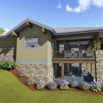
Autocad Drawing And Coohom Design 3d Fast Rendering Blog

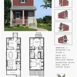
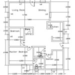
First Floor Plan Of Residence Detail Presented In This Autocad Drawing File 2d Auto Cad Ca Layout

Is Autocad The Best Floor Plan For Estate Agents Elements Property

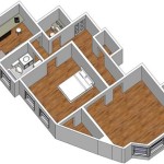
Floor Plan Create 2d 3d Plans Autodesk

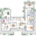
North Facing House Plan Drawing Autocad File Cadbull

Autocad Simple Floor Plan For Beginners 1 Of 5

Autocad Tutorial Draw A House Floor Plan Free Cad Blocks In Dwg File Format
Related Posts