How To Draw a Floor Plan in AutoCAD 2024
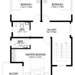
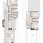
AutoCAD 2024 is a powerful computer-aided design (CAD) software widely used by architects, engineers, and designers to create precise 2D and 3D drawings. One of the most fundamental applications of AutoCAD is the creation of floor plans. A floor plan is a scaled diagram of a room or building viewed from above, providing a visual representation of the layout, including walls, doors, windows, and other architectural features. This article will guide you through the essential steps involved in drawing a floor plan using AutoCAD 2024.
Before initiating the drawing process, it is crucial to have a clear understanding of the project requirements. This includes the dimensions of the building, the placement of rooms, the desired style, and any specific needs or regulations that must be followed. Gathering accurate measurements is paramount; these can be obtained through on-site surveys using measuring tapes, laser distance measurers, or by referencing existing architectural drawings.
Prior to commencing the drawing process, setting up AutoCAD’s environment is essential for ensuring accuracy and efficiency. This involves configuring the units, setting the drawing limits, and establishing layers. Proper layer management is critical for organizing the various elements of the floor plan, allowing for easy modification and visibility control.
1. Setting Up AutoCAD for Floor Plan Creation
The initial step involves configuring the AutoCAD environment to ensure accuracy and ease of drawing. This includes setting units, defining drawing limits, and establishing appropriate layers.
Units: Open a new drawing in AutoCAD 2024. The default template may already have units configured, but it’s essential to verify and adjust them if necessary. Type "UNITS" in the command line and press Enter. This opens the Drawing Units dialog box. Here, you can select the appropriate unit of measurement, such as architectural (feet and inches), decimal (meters or millimeters), or engineering. Choose the precision level that suits the project's requirements. For architectural drawings, selecting "Architectural" with a precision of 1/16" is common. Click "OK" to save the settings.
Drawing Limits: Drawing limits define the area in the model space where the drawing will be created. This is a helpful parameter for visually understanding the extent of the drawing. Type "LIMITS" in the command line and press Enter. AutoCAD will prompt you to specify the lower-left corner. Enter "0,0" and press Enter. Next, it will ask for the upper-right corner. This depends on the size of the floor plan. For a typical house, you might enter "50',40'" (50 feet by 40 feet) or a similar value. Remember to match the units set earlier. After setting the limits, type "ZOOM" and press Enter, then type "A" (for All) and press Enter. This will zoom the drawing area to fit the defined limits.
Layers: Layers are fundamental for organizing and controlling the different elements of the floor plan. Create layers for Walls, Doors, Windows, Furniture, Dimensions, and Text. To create layers, type "LAYER" in the command line and press Enter. This opens the Layer Properties Manager. Click the "New Layer" icon (or press Alt+N) to create a new layer. Name the layer appropriately (e.g., "Walls"). Assign a color to each layer to easily differentiate them visually. For example, use red for walls, blue for windows, and green for doors. You can also adjust the linetype and lineweight for each layer to further enhance clarity. Repeat this process for all the necessary layers. Ensure that the “Walls” layer is set as the current layer before starting to draw the walls.
Proper layer management allows for efficient modification and visibility control. For example, toggling the visibility of the “Furniture” layer allows you to hide or show furniture while working on other aspects of the floor plan.
2. Drawing Walls, Doors, and Windows
With the drawing environment set up, the next step is to draw the walls, doors, and windows, which form the structural framework of the floor plan.
Drawing Walls: Walls are the primary structural elements of a floor plan. Select the "Walls" layer as the current layer. Use the "LINE" command (type "L" and press Enter) to draw the exterior walls. Define the starting point by clicking on the drawing area or entering coordinates. Enter the length of the wall and the angle (if not horizontal or vertical). You can use Ortho mode (press F8) to constrain the lines to horizontal or vertical directions, ensuring accuracy. Continue drawing the walls, following the external dimensions of the building. Use the "OFFSET" command (type "O" and press Enter) to create the thickness of the walls. Enter the offset distance (e.g., 6 inches for interior walls, 9 inches for exterior walls) and select the line representing the exterior wall. Click inside the shape to create the interior wall line. Use the "TRIM" command (type "TR" and press Enter) to clean up the corners and intersections of the walls. Select all the lines and press Enter, then click on the portions of the lines you want to remove to create clean wall intersections.
Creating Doors: Doors provide access between rooms and to the exterior. First, determine the location and width of each door. Use the "LINE" command to create a line representing the opening for the door. This line should be slightly longer than the door width. Use the "OFFSET" command to create two lines that represent the door opening width, offsetting from a starting reference point. Again, use the "TRIM" command to remove the portions of the wall lines within the opening. Create a new layer called “Doors” and set it as current. To represent the door itself, draw a rectangle using the "RECTANGLE" command (type "REC" and press Enter) within the opening, representing the door panel. Use the "ARC" command (type "A" and press Enter) to draw an arc indicating the direction of the door swing. Specify the start point, second point, and end point of the arc. The arc should start at the hinge side of the door and end at the opposite side, indicating the swing direction.
Adding Windows: Windows provide light and ventilation. Determine the location and width of each window. Use the "LINE" command to create the opening for the window. Use the "OFFSET" command to create two lines that represent the window opening width, offsetting from a starting reference point. Use the "TRIM" command to remove the portions of the wall lines within the opening. Create a new layer called “Windows” and set it as current. Draw a line across the center of the window opening to represent the window pane. You can add additional lines to represent window frames or sashes, depending on the desired level of detail.
When drawing walls, doors, and windows, pay close attention to the accuracy of the dimensions and the placement of these elements. Use object snaps (OSNAP), such as Endpoint, Midpoint, and Intersection, to precisely align the lines and ensure the accuracy of the drawing.
3. Adding Interior Features and Annotations
After establishing the structural framework, add interior features such as furniture, fixtures, and appliances to the floor plan. Annotations, including dimensions, text, and symbols, are crucial for providing essential information and clarity.
Adding Interior Features: Create separate layers for different types of interior features, such as "Furniture," "Fixtures," and "Appliances." These layers will help organize and control the visibility of these elements. Use the "INSERT" command (type "I" and press Enter) to insert pre-drawn blocks representing furniture, fixtures, and appliances. AutoCAD comes with a library of standard blocks, or you can download or create custom blocks. Common furniture items include beds, sofas, chairs, tables, and cabinets. Fixtures include sinks, toilets, bathtubs, and showers. Appliances include refrigerators, stoves, ovens, and dishwashers. Position the blocks in the appropriate locations within the floor plan. Use the "MOVE" (type "M" and press Enter) and "ROTATE" (type "RO" and press Enter) commands to adjust the position and orientation of the blocks. Ensure that the furniture and fixtures are drawn to scale and accurately represent their sizes and shapes.
Adding Dimensions: Dimensions provide critical information about the sizes and locations of different elements within the floor plan. Create a "Dimensions" layer and set it as current. Use the "DIMLINEAR" command (type "DLI" and press Enter) to create linear dimensions. Specify the start point and end point of the dimension, and then click to place the dimension line. Adjust the dimension settings, such as text size, arrow size, and units, to ensure that the dimensions are clear and legible. Use the "DIMCONTINUE" command (type "DCO" and press Enter) to create a series of continuous dimensions. This is useful for dimensioning a series of walls or openings along a straight line. Add overall dimensions to indicate the total size of the building or rooms. Add dimensions for door and window openings, wall thicknesses, and furniture placements.
Adding Text and Symbols: Text and symbols are used to provide additional information and clarify the floor plan. Create a "Text" layer and a "Symbols" layer. Use the "TEXT" command (type "T" and press Enter) to add text annotations to the floor plan. Label each room with its name (e.g., "Living Room," "Bedroom," "Kitchen"). Add notes to indicate specific features or materials (e.g., "Fireplace," "Hardwood Flooring"). Use symbols to represent electrical outlets, light switches, plumbing fixtures, and other elements. AutoCAD includes a library of standard symbols, or you can create custom symbols. Insert the symbols into the floor plan and position them appropriately. Adjust the text size, font, and color to ensure that the text is legible and consistent with the overall drawing style.
When adding interior features and annotations, maintain consistency and clarity. Use a consistent scale, font size, and dimension style throughout the floor plan. Ensure that all text and symbols are legible and easy to understand. Regularly review the floor plan to identify and correct any errors or inconsistencies.
By following these steps, you can create accurate and professional floor plans in AutoCAD 2024, which can then be used for construction, renovation, or documentation purposes. The process requires attention to detail, accuracy, and a thorough understanding of architectural principles.

Autocad 2024 Tutorial Making A Simple Floor Plan In 2d Drawing

Autocad 2024 Tutorial Making A Simple Floor Plan In 2d Drawing

Autocad 2024 Making A Simple Floor Plan In Part 1 Of 3 2d Drawing 2025

Basic Floor Plan Drafting In Autocad 7 Steps Instructables

Autocad 2024 Tutorial Making A Simple Floor Plan In 2d Drawing

Draw Floor Plan And Elevation Using Basic Autocad Commands Acad Systems Autodesk Gold Partner Training Certification Center

How To Draw Floor Plans In Autocad Edrawmax

Making A Simple Floor Plan In Autocad Part 1 Of 3

Autocad Lt 2024 Help File Tab Menu Autodesk

Autocad 2024 Help What S New In Map 3d Toolset Autodesk
Related Posts

