How To Draw a One-Bedroom Floor Plan In AutoCAD
AutoCAD is a powerful computer-aided design (CAD) software widely used in architecture, engineering, and construction for creating precise 2D and 3D drawings. Drawing a one-bedroom floor plan in AutoCAD involves a systematic process, requiring attention to detail and adherence to standard architectural conventions. This article provides a comprehensive guide on how to create a one-bedroom floor plan in AutoCAD, covering essential steps from setting up the drawing environment to adding annotations and dimensions.
1. Setting Up the AutoCAD Drawing Environment
Before starting the actual drawing process, it's crucial to configure the AutoCAD environment to ensure accuracy and efficiency. This involves setting units, establishing limits, creating layers, and defining styles for text and dimensions. These initial configurations significantly impact the overall quality and readability of the floor plan.
Setting Units: The first step is to set the drawing units. In AutoCAD, type "UNITS" in the command line and press Enter. The Drawing Units dialog box will appear. Choose the desired units, such as architectural (feet and inches) or decimal (meters), from the "Units to scale inserted content" dropdown menu. Precision should also be specified, depending on the level of detail required for the floor plan. Architectural units typically use fractional precision, while decimal units use decimal precision.
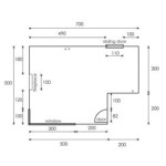
Establishing Limits: Next, the drawing limits need to be defined. These limits represent the boundaries of the drawing area and help in managing the drawing scale. Type "LIMITS" in the command line and press Enter. AutoCAD will prompt for the lower-left corner, which is typically set to 0,0. Then, it will ask for the upper-right corner. Enter appropriate coordinates based on the expected size of the floor plan. For example, if the one-bedroom apartment is expected to be 30 feet by 40 feet, the upper-right corner could be set to 30',40'. After setting the limits, type "ZOOM" and then "A" (for "All") to ensure the entire drawing area is visible.
Creating Layers: Layers are essential for organizing different elements of the floor plan. Creating separate layers for walls, windows, doors, furniture, and dimensions allows for easy modification and control of visibility. To create layers, type "LAYER" in the command line and press Enter. The Layer Properties Manager will appear. Click the "New Layer" icon to create new layers. Assign descriptive names to each layer, such as "Walls," "Windows," "Doors," "Furniture," and "Dimensions." Assign different colors and lineweights to each layer for visual distinction. For example, walls might be assigned a thicker lineweight and a dark color, while dimensions might be assigned a thinner lineweight and a lighter color. It is also helpful to set the linetype for hidden elements, such as plumbing, to a dashed or hidden linetype.
Defining Text and Dimension Styles: Configuring text and dimension styles ensures consistency and readability throughout the floor plan. To define text styles, type "STYLE" in the command line and press Enter. The Text Style dialog box will appear. Create a new text style by clicking "New." Choose a suitable font, such as Arial or Times New Roman, and set the text height. Similarly, to define dimension styles, type "DIMSTYLE" in the command line and press Enter. The Dimension Style Manager will appear. Create a new dimension style by clicking "New." Modify the settings for lines, symbols and arrows, text, fit, and primary units to match the desired appearance. Ensure that the dimension text is legible and that the arrows and extension lines are appropriately sized.
2. Drawing the Basic Architectural Elements
With the drawing environment properly set up, the next step is to draw the basic architectural elements of the one-bedroom floor plan, including walls, doors, and windows. Accuracy and adherence to standard architectural dimensions are crucial at this stage.
Drawing Walls: Start by drawing the exterior walls of the apartment. Use the "LINE" command (type "L" and press Enter) or the "PLINE" command (type "PL" and press Enter) to draw the walls. The "PLINE" command creates a continuous polyline, which is often preferred for drawing walls. Ensure the "ORTHO" mode (press F8) is enabled to draw straight lines. Enter the coordinates or distances for each wall segment. The standard wall thickness for residential buildings is typically 4 to 6 inches for interior walls and 6 to 8 inches for exterior walls. Offset the lines by the appropriate wall thickness using the "OFFSET" command (type "O" and press Enter). Specify the offset distance (e.g., 6 inches) and select the lines to offset. Close the wall boundaries by connecting the endpoints of the offset lines.
Creating Door Openings: Next, create openings for doors. Determine the locations and sizes of the door openings. Standard door widths for interior doors are typically 30 or 32 inches. Use the "LINE" command to draw the door openings on the wall layer. Use the "TRIM" command (type "TR" and press Enter) to remove the portions of the wall lines within the door opening. Select the cutting edges (the lines defining the door opening) and press Enter. Then, select the objects to trim (the wall lines) and press Enter. Add a door swing using the "ARC" command (type "A" and press Enter). Specify the start point, center point, and end point of the arc to represent the door swing. Place the door on the appropriate layer.
Adding Windows: Similarly, add windows to the floor plan. Determine the locations and sizes of the windows. Standard window widths vary depending on the design and the amount of natural light desired. Use the "LINE" command to draw the window openings on the wall layer. Use the "OFFSET" command to create the window frame. Use the "TRIM" command to remove the portions of the wall lines within the window opening. Add window panes using the "LINE" command. Place the windows on the appropriate layer.
3. Adding Interior Details and Annotations
After drawing the basic architectural elements, the next step is to add interior details such as furniture, fixtures, and appliances, as well as annotations and dimensions. This step enhances the clarity and completeness of the floor plan.
Adding Furniture, Fixtures, and Appliances: Insert furniture blocks, such as beds, sofas, tables, and chairs, into the floor plan. AutoCAD provides a library of pre-drawn blocks that can be inserted into the drawing. Type "INSERT" in the command line and press Enter. The Insert dialog box will appear. Browse for the desired block file or use the DesignCenter to access a wider range of blocks. Specify the insertion point, scale, and rotation angle for the block. Place the furniture blocks on the furniture layer. Similarly, add fixtures such as sinks, toilets, and bathtubs, and appliances such as refrigerators, stoves, and washing machines. Ensure that the furniture and fixtures are appropriately sized and positioned within the floor plan.
Adding Annotations: Annotations provide additional information about the floor plan, such as room names, dimensions, and notes. Use the "TEXT" command (type "TEXT" or "MTEXT" and press Enter) to add text annotations. "TEXT" creates single-line text, while "MTEXT" creates multi-line text. Specify the start point, text height, and rotation angle for the text. Type the desired text, such as "Bedroom," "Living Room," "Kitchen," and "Bathroom." Place the text annotations on the annotation layer. Use leaders to point to specific features or areas in the floor plan. The "LEADER" command (type "LEADER" and press Enter) allows you to create arrows or lines that connect text annotations to specific points on the drawing.
Adding Dimensions: Dimensions are crucial for indicating the sizes and locations of different elements in the floor plan. Use the "DIMLINEAR" command (type "DIMLINEAR" and press Enter) to create linear dimensions. Specify the first and second extension line origins, and then specify the dimension line location. AutoCAD will automatically calculate and display the dimension value. Use the "DIMCONTINUE" command (type "DIMCONTINUE" and press Enter) to create a series of continuous dimensions. Use the "DIMRADIUS" and "DIMDIAMETER" commands to dimension arcs and circles, respectively. Ensure that the dimensions are clear, accurate, and easy to read. Place the dimensions on the dimension layer.
Hatching and Fill: Hatching can be used to indicate different materials or finishes in the floor plan. Use the "HATCH" command (type "HATCH" and press Enter) to add hatching. The Hatch Creation dialog box will appear. Choose a hatch pattern, such as solid fill, brick, or tile. Specify the scale and angle for the hatch pattern. Select the area to be hatched by clicking inside the boundary. Preview the hatch pattern and adjust the settings as needed. Place the hatching on the hatching layer.
By following these steps, a detailed and accurate one-bedroom floor plan can be created in AutoCAD. The meticulous attention to detail in setting up the drawing environment, drawing the basic architectural elements, and adding interior details and annotations contributes to a professional-quality floor plan suitable for architectural design and construction purposes.

Drawing One Bed Room Floor Plan In Auto Cad

Making A Simple Floor Plan In Autocad Part 1 Of 3

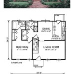
1 A Bedroom Flat Home Architectural Design In Autocad Setting The Units And Drawing Limits

Basic Floor Plan Drafting In Autocad 7 Steps Instructables

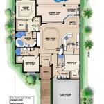
1 Bedroom House Ground Floor Plan Autocad Drawing Dwg File

One Bhk House Plan Drawing In Autocad

How To Draw Perfect Floor Plans In Autocad Part 1

How To Draw Floor Plans In Autocad Edrawmax

Drawing One Bed Room Floor Plan In Auto Cad

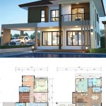
A One Bedroom Villa Arch Floor Plan Elevation In Autocad 2d Jpg Upwork
Related Posts