How to Draw a Floor Plan of a House
Drawing a floor plan is a fundamental skill for architects, interior designers, real estate professionals, and homeowners alike. A well-executed floor plan visually represents the layout of a building, providing a clear understanding of spatial relationships, dimensions, and the arrangement of rooms and features. This detailed guide outlines the process of creating an accurate and informative floor plan, from initial measurements to the final presentation.
Before commencing the drawing process, it is crucial to gather the necessary tools and equipment. This typically includes a measuring tape (preferably a laser distance measurer for larger spaces), a pencil, an eraser, graph paper or architectural paper, a straightedge or ruler, and a protractor or set square. Access to a computer-aided design (CAD) software program can greatly enhance the accuracy and efficiency of the drawing process, although traditional hand-drawing methods remain valuable for initial sketches and concept development.
The initial step involves accurately measuring the existing structure. This requires systematically measuring the length and width of each room, as well as the thickness of the walls. Pay close attention to architectural features such as doorways, windows, columns, and fireplaces. Precise measurements are paramount, as even small inaccuracies can compound and result in a significantly flawed floor plan. It is advisable to measure each dimension multiple times to ensure consistency and reliability.
When measuring, it is useful to create a rough sketch on a piece of paper to record measurements as they are taken. This sketch should include an outline of the building's perimeter and the approximate location of interior walls. As each dimension is measured, immediately record it on the sketch, clearly labeling which measurement corresponds to which wall or feature. This preliminary sketch serves as a vital reference point during the detailed drawing phase.
Following the measurement phase, the next step is to transfer the measurements to the graph paper or architectural paper. This involves carefully scaling the measurements to fit the paper size. A commonly used scale for residential floor plans is 1/4 inch equals 1 foot, or 1:50 scale if using metric measurements. This means that every quarter inch on the paper represents one foot in the actual building. Consistency with the selected scale is essential for maintaining the proportionality and accuracy of the floor plan. Start by drawing the exterior walls, ensuring that the corners are square and the lengths correspond to the measured dimensions. Use a straightedge to create clean, straight lines.
Once the exterior walls are drawn, proceed to draw the interior walls. Again, ensure that the walls are drawn to scale and that they are positioned accurately relative to the exterior walls and to each other. Pay close attention to the thickness of the walls, as this can significantly impact the interior dimensions of the rooms. Indicate the location of doorways and windows by leaving gaps in the walls at the appropriate locations. The width of these gaps should correspond to the actual width of the door and window openings.
After drawing the walls, the next step is to add architectural features such as doors, windows, stairs, and fireplaces. Doors are typically represented by an arc showing the direction of the door swing. Windows are represented by parallel lines within the wall, indicating the window frame. Stairs are shown with a series of parallel lines indicating the steps, and an arrow indicating the direction of ascent. Fireplaces are represented by a rectangular shape indicating the hearth and chimney breast. Standard architectural symbols are used for these elements to ensure clarity and consistency.
Furniture placement can be indicated on the floor plan to provide a sense of the room's scale and functionality. This is typically done by drawing simplified representations of furniture items such as sofas, beds, tables, and chairs. The size and placement of furniture can influence the circulation patterns within the room and the overall usability of the space. While detailed representations are not necessary, the furniture symbols should be drawn to scale to accurately represent the space occupied by the furniture.
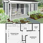
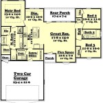
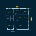
Once the basic floor plan is complete, it is important to add annotations to provide additional information. This includes labeling each room with its name, such as "Living Room," "Bedroom," or "Kitchen." Dimensions should also be added to the floor plan, indicating the length and width of each room and the overall dimensions of the building. Annotations should be clear, concise, and easy to read. It is also helpful to include a north arrow on the floor plan to indicate the orientation of the building.
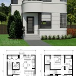
For those using CAD software, the process is streamlined with digital tools offering precise measurement input, automatic scaling, and a library of pre-designed architectural symbols. CAD programs also facilitate modifications and revisions, allowing for easy adjustments to the floor plan as needed. Moreover, CAD software enables the creation of 3D models from the 2D floor plan, providing a more comprehensive visualization of the space.
Key Point 1: Accurate Measurement is Paramount
The foundation of any successful floor plan is accurate measurement. Inaccurate measurements will lead to a flawed floor plan that does not accurately represent the building. This can have significant consequences, especially during construction or renovation projects. It is crucial to take the time to measure each dimension carefully and to verify the measurements multiple times. The use of a laser distance measurer can greatly improve the accuracy and efficiency of the measuring process.
When measuring a room, measure the length and width at multiple points to account for any irregularities in the walls. If the walls are not perfectly straight, take measurements at the longest and shortest points and average them to obtain a more accurate representation of the room's dimensions. Similarly, when measuring doorways and windows, measure the width of the opening at the top, middle, and bottom to ensure that the measurements are consistent.
Document all measurements meticulously, including the thickness of walls, the placement of doors and windows, and the location of any architectural features. A detailed sketch with labeled measurements will serve as an invaluable reference point throughout the drawing process, preventing errors and ensuring the accuracy of the final floor plan.
Key Point 2: Choosing the Appropriate Scale
Selecting the correct scale is essential for effectively representing the building on paper. The scale determines the relationship between the dimensions on the floor plan and the actual dimensions of the building. A commonly used scale for residential floor plans is 1/4 inch equals 1 foot, which provides a balance between detail and manageability. However, the appropriate scale may vary depending on the size of the building and the level of detail required.
For larger buildings, a smaller scale such as 1/8 inch equals 1 foot may be necessary to fit the entire floor plan on a single sheet of paper. Conversely, for smaller rooms or areas requiring a high level of detail, a larger scale such as 1/2 inch equals 1 foot may be more appropriate. Regardless of the scale chosen, it is imperative to maintain consistency throughout the drawing process.
Understanding the implications of the chosen scale is vital. A smaller scale will allow for the representation of a larger area but with less detail. A larger scale will provide more detail but will limit the area that can be represented on a single sheet. Careful consideration should be given to the purpose of the floor plan and the level of detail required when selecting the appropriate scale.
Key Point 3: Understanding Architectural Symbols
Floor plans often utilize standardized architectural symbols to represent various building elements and features. These symbols provide a consistent and universally understood method of communication, ensuring that the floor plan can be easily interpreted by architects, contractors, and other professionals. Familiarity with these symbols is essential for accurately reading and creating floor plans.
Common architectural symbols include those for doors (represented by an arc indicating the swing direction), windows (represented by parallel lines within the wall), stairs (represented by a series of parallel lines with an arrow indicating the direction of ascent), and plumbing fixtures (represented by stylized shapes indicating the location of sinks, toilets, and showers). A comprehensive list of architectural symbols can be found in architectural drafting textbooks or online resources.
Using the correct symbols and adhering to established conventions ensures clarity and avoids ambiguity. A well-drawn floor plan with clearly defined symbols facilitates communication and reduces the likelihood of errors during the design and construction process. Furthermore, consistent use of symbols demonstrates professionalism and attention to detail.
Beyond the core elements of measurement, scaling, and symbol usage, consider the overall clarity and legibility of the floor plan. Employ clean, crisp lines and avoid unnecessary clutter. Use a consistent lettering style for annotations and labels. If using color, do so sparingly and purposefully to highlight specific features or zones. The goal is to create a floor plan that is both informative and aesthetically pleasing, effectively communicating the design intent of the building.
The creation of a floor plan is an iterative process that may require multiple revisions. As the design evolves, the floor plan should be updated to reflect any changes. Regular review and refinement of the floor plan ensures that it remains accurate and reflective of the current design. Whether hand-drawn or computer-generated, a well-executed floor plan is an invaluable tool for visualizing and communicating the spatial organization of a building.

How To Draw A Floor Plan Live Home 3d

How To Draw Floor Plans With Floorplanner Com Young House Love

Floor Plans Learn How To Design And Plan

How To Draw A Floor Plan The Simple 7 Step Guide For 2024

Draw Floor Plans To Scale With Symbols Dimensions Cedreo

How To Draw Blueprints For A House With Pictures Wikihow

12 Examples Of Floor Plans With Dimensions

Create Floor Plan

Make Your Own Blueprint How To Draw Floor Plans

Drawing Floor Plan 101 Basic Principles Esoft
Related Posts