Draw A Home Floor Plan: A Comprehensive Guide
Creating a home floor plan is a fundamental step in any construction, renovation, or interior design project. A well-crafted floor plan provides a visual representation of a space, outlining room dimensions, wall placements, door and window locations, and other key architectural elements. This document serves as a blueprint for builders, contractors, and designers, ensuring accurate execution and minimizing potential errors.
Regardless of the project's scale, understanding the basics of drawing a home floor plan is invaluable. This article aims to provide a comprehensive overview of the process, covering essential tools, techniques, and considerations for creating effective and informative home floor plans.
Choosing the Right Tools and Materials
The first step in drawing a home floor plan is assembling the necessary tools and materials. The choice between manual drafting and digital software depends largely on the individual's preference, budget, and the complexity of the project. Each approach offers distinct advantages and disadvantages.
For manual drafting, the following tools are essential:
Graph Paper:
Provides a grid for accurate scaling and alignment. A scale of ¼ inch per foot is commonly used, though other scales may be appropriate depending on the size of the building.Pencils:
A set of pencils with varying lead hardness (e.g., 2H, HB, 2B) allows for different line weights and shading. A mechanical pencil with a consistent lead size is particularly useful for precise lines.Eraser:
A good-quality eraser is crucial for correcting mistakes and cleaning up lines. A kneaded eraser is ideal for lifting graphite without damaging the paper.Ruler and Triangle:
These tools are essential for drawing straight lines and accurate angles. A T-square can also be helpful for drawing horizontal lines.Compass:
Used for drawing circles and arcs, particularly for architectural details such as arched doorways or curved walls.Architectural Scale Ruler:
A specialized ruler with multiple scales marked on it, allowing for direct measurement and scaling of drawings. This is a vital tool for architects and designers.
For digital drafting, several software options are available, ranging from free, basic programs to professional-grade applications:
Free Online Tools:
Numerous websites offer free floor plan creators with basic functionality. These tools are suitable for simple projects and quick sketches. Examples include Floorplanner and RoomSketcher.Entry-Level Software:
Programs like SketchUp offer a balance of ease of use and powerful features. They are suitable for homeowners and DIY enthusiasts who want to create more detailed floor plans.Professional CAD Software:
Computer-Aided Design (CAD) software such as AutoCAD and Revit are industry standards for architects and engineers. These programs offer advanced features for creating highly accurate and detailed drawings. However, they typically require significant training and a paid subscription.
Regardless of the chosen method, it is imperative to gather accurate measurements of the existing space. A laser measuring tool can significantly improve accuracy and efficiency compared to traditional measuring tapes. Documenting existing features such as doors, windows, electrical outlets, and plumbing fixtures is also crucial.
Understanding Scale and Conventions
A floor plan is a scaled-down representation of a real-world space. Using a consistent and accurate scale is essential for ensuring that the drawing accurately reflects the actual dimensions of the building. The scale indicates the relationship between the distances on the drawing and the corresponding distances in the real world.
Common architectural scales include:
1/4" = 1' 0":
One-quarter inch on the drawing represents one foot in reality. This scale is commonly used for residential floor plans.1/8" = 1' 0":
One-eighth inch on the drawing represents one foot in reality. This scale is suitable for larger buildings or when a smaller drawing size is desired.1/2" = 1' 0":
One-half inch on the drawing represents one foot in reality. This scale provides greater detail but requires a larger drawing size.
In addition to scale, floor plans utilize standard conventions to represent different architectural elements. These conventions ensure that the drawing is easily understood by anyone familiar with architectural drafting practices.
Common conventions include:
Walls:
Typically represented by thick, solid lines. The thickness of the lines can vary to differentiate between exterior and interior walls.Doors:
Represented by an arc indicating the swing direction and a line connecting the door to the wall. The door width is indicated by the length of the door symbol.Windows:
Represented by two or three parallel lines, indicating the window frame and glass. The window width and type (e.g., single-hung, double-hung, sliding) should be clearly indicated.Stairs:
Represented by a series of parallel lines indicating the steps, with arrows indicating the direction of ascent. The number of steps and the riser height should be noted.Plumbing Fixtures:
Sinks, toilets, bathtubs, and showers are represented by standard symbols that are easily recognizable.Electrical Outlets and Switches:
Represented by standard symbols that indicate the type of outlet or switch (e.g., duplex outlet, single-pole switch).
A legend or key should be included with the floor plan to explain any symbols or abbreviations used. This ensures that the drawing is clear and unambiguous.
Steps for Drawing a Floor Plan
The process of drawing a home floor plan typically involves the following steps:
Sketch the Exterior Walls:
Begin by sketching the outline of the exterior walls on the graph paper or in the digital software. Use the chosen scale to accurately represent the wall lengths and thicknesses. Ensure that the corners are square and that the overall shape matches the building's footprint.Draw Interior Walls:
Add the interior walls, using accurate measurements to determine their locations and thicknesses. Consider the placement of load-bearing walls, which may require thicker lines to indicate their structural importance.Place Doors and Windows:
Indicate the locations of doors and windows, using the appropriate symbols and dimensions. Consider the swing direction of doors and the type of windows being used. Ensure that the door and window openings are accurately sized and positioned.Add Plumbing Fixtures:
Place plumbing fixtures in their respective locations, using standard symbols to represent sinks, toilets, bathtubs, and showers. Indicate the location of water supply lines and drain pipes.Add Electrical Outlets and Switches:
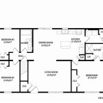
Indicate the locations of electrical outlets and switches, using standard symbols to represent the type of outlet or switch. Consider the placement of furniture, appliances, and lighting fixtures when determining the placement of electrical outlets.Label Rooms and Features:
Label each room with its name (e.g., living room, bedroom, kitchen). Add labels for other key features such as closets, hallways, and staircases. Indicate the dimensions of each room and the overall dimensions of the building.Add Notes and Details:
Include any additional notes or details that are relevant to the floor plan, such as the type of flooring, wall finishes, or ceiling heights. Add a north arrow to indicate the orientation of the building.Review and Refine:
Carefully review the floor plan for accuracy and completeness. Check that all dimensions are correct, that all symbols are used correctly, and that all features are clearly labeled. Make any necessary corrections or refinements.
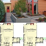
For complex projects, it may be helpful to create multiple floor plans, each focusing on a specific aspect of the building. For example, one floor plan might show the layout of the rooms, while another might show the plumbing and electrical systems. This approach can help to simplify the drawing process and make the information more accessible.
Digital software often allows for the creation of 3D models from the 2D floor plan. This can be a valuable tool for visualizing the space and identifying potential design issues. Many programs also offer features for generating schedules of materials and finishes, which can be helpful for budgeting and purchasing.
Creating a home floor plan requires careful planning, attention to detail, and a thorough understanding of architectural principles. Whether using manual drafting techniques or digital software, the key is to create a clear, accurate, and informative drawing that effectively communicates the design intent.

Floor Plan Creator And Designer Free Easy App

Floor Plans Types Symbols Examples

House Plans How To Design Your Home Plan

Floor Plans Types Symbols Examples

House Plan Drawing Everything You Need To Know

Draw Floor Plans In Half The Time Cedreo

Home Floor Plans House Plan Drawings

Draw Floor Plans In Half The Time Cedreo

Easy Home Building Floor Plan Cad Pro

House Plans How To Design Your Home Plan
Related Posts