Civil 2D Plan With Dimensions: A Comprehensive Overview
Civil 2D is a powerful software used extensively in civil engineering for designing, drafting, and documenting infrastructure projects. One of its core functionalities involves creating comprehensive civil 2D plans incorporating precise dimensions. These plans serve as the foundation for construction, ensuring accurate execution of the design. The integration of dimensions within a Civil 2D plan is crucial for conveying the intended size, shape, and location of various elements, facilitating collaboration between engineers, contractors, and surveyors.
A civil 2D plan with dimensions typically depicts a top-down view of the project site, showcasing key features such as property lines, existing utilities, proposed structures, grading plans, roadways, and drainage systems. The inclusion of accurate dimensions is paramount for translating the design concept into a buildable reality. Without precise measurements, ambiguities can arise, leading to construction errors, delays, and increased costs. Therefore, understanding the process of creating and interpreting civil 2D plans with dimensions is essential for professionals involved in civil engineering projects.
The accuracy and clarity of dimensions are directly related to the success of the project. Dimensions on a civil 2D plan need to be easily understood by all stakeholders. Clarity is promoted through standardized dimensioning practices and the use of appropriate units. Inconsistent or ambiguous dimensioning can lead to misinterpretations, which can result in variations from the design intent and potential structural or functional problems within the constructed infrastructure.
The utilization of Civil 2D software offers a range of tools and features to streamline the dimensioning process. The software allows for the creation of various types of dimensions, including linear, aligned, angular, radial, and coordinate dimensions. These dimensions can be customized to meet specific project requirements and drafting standards. Furthermore, Civil 2D provides functionalities for automatically updating dimensions as the design changes, ensuring that the plan remains accurate throughout the project lifecycle. The ability to automatically update dimensions is a significant advantage over manual drafting methods, as it minimizes the risk of errors and saves valuable time.
Understanding Dimensioning Standards and Conventions
Effective civil 2D plans with dimensions conform to established industry standards and conventions. These standards ensure uniformity and facilitate the interpretation of the plan by different parties involved in the project. One of the most common standards used in civil engineering is the ANSI (American National Standards Institute) standard. ANSI Y14.5M-1994, for example, provides guidelines for dimensioning and tolerancing. Other standards, like those used within specific state or local departments of transportation, might also be relevant, depending on the project's geographic location and regulatory context.
Dimensioning conventions encompass various aspects, including the placement of dimension lines, extension lines, arrowheads, and text. Dimension lines indicate the direction and extent of the dimension, while extension lines extend from the object being dimensioned to the dimension line. Arrowheads terminate the dimension line and point to the features being measured. Dimension text, typically placed above or adjacent to the dimension line, displays the numerical value of the dimension. Consistent application of these conventions enhances the readability and clarity of the plan. For example, small dimensions are generally placed inside the extension lines, while larger dimensions are placed outside. All dimensions must be legible and not overlap with other plan elements.
Units of measurement should be clearly specified on the plan. Common units used in civil engineering include feet, inches, meters, and millimeters. The choice of units depends on the scale of the project and the preferences of the design team. Consistency in units is vital to avoid confusion and errors. If a combination of units is needed, a clear explanation must be provided in the drawing notes or legends. Some organizations require the use of specific decimal precision for different types of dimensions within a civil plan.
Furthermore, the use of leaders and annotations plays a significant role in clarifying dimensions and providing additional information. Leaders are lines that connect a dimension or annotation to a specific feature on the plan. Annotations are text notes that provide further details about the feature or dimension. Leaders should be clear and concise, pointing directly to the feature being described. Annotations should be brief and informative, providing necessary context without cluttering the plan. A clear and consistent system of annotation is critical for conveying complex information in an accessible and easily understood manner.
Key Considerations for Creating Accurate Dimensions in Civil 2D
Creating accurate dimensions in Civil 2D requires careful attention to detail and a thorough understanding of the software's capabilities. Several key considerations must be taken into account to ensure that the dimensions on the plan are reliable and reflect the true measurements of the designed elements. These considerations include setting the correct drawing scale, utilizing appropriate object snaps, and verifying dimensions against known references.
The drawing scale is a critical parameter that determines the relationship between the dimensions on the plan and the actual dimensions on the ground. It is essential to set the correct drawing scale at the beginning of the project to avoid scaling errors. The drawing scale should be chosen based on the size of the project site and the level of detail required. A larger scale (e.g., 1:100) allows for more detail but may require a larger drawing sheet. A smaller scale (e.g., 1:1000) is suitable for larger areas but may sacrifice detail. The selected scale must be clearly indicated on the plan for reference.
Object snaps are tools that allow users to precisely select specific points on objects, such as endpoints, midpoints, intersections, and centers. Accurate use of object snaps is crucial for ensuring that dimensions are correctly placed and aligned. Civil 2D provides a variety of object snaps that can be enabled or disabled as needed. By using object snaps, designers can avoid manually selecting points, which can be prone to errors. For example, using the "endpoint" object snap ensures that a dimension is accurately placed at the end of a line or polyline.
Dimensions should be regularly verified against known references to ensure their accuracy. These references can include existing survey data, control points, or other reliable sources of information. By comparing the dimensions on the plan to these references, designers can identify and correct any discrepancies. Verification should be performed at various stages of the design process, including initial drafting, design revisions, and final plan preparation. This practice helps to minimize errors and ensure that the plan accurately reflects the intended design.
The dynamic nature of Civil 2D allows for parametric design, meaning that changes made to one element can automatically update related dimensions and features. This feature is beneficial for maintaining consistency and accuracy throughout the design process. However, it is crucial to understand how these dynamic relationships are defined and managed to avoid unintended consequences. Always review the impacts of design changes on dimensions and ensure that the plan accurately reflects the revised design.
Common Dimensioning Errors and How to Avoid Them
Despite the availability of advanced tools and techniques, errors can still occur during the dimensioning process in Civil 2D. These errors can range from minor inaccuracies to significant misrepresentations that can have serious consequences during construction. Understanding common dimensioning errors and implementing strategies to avoid them is crucial for ensuring the quality and reliability of civil 2D plans.
One common error is the omission of dimensions. Leaving out critical dimensions can create ambiguity and make it difficult for contractors to accurately construct the design. To avoid omissions, it is essential to systematically dimension all relevant features and aspects of the project. A checklist can be used to ensure that all necessary dimensions are included. Alternatively, using a layered approach to dimensioning, where dimensions are progressively added as the design develops, can help to identify and address any gaps.
Overlapping or conflicting dimensions can also lead to confusion and errors. Overlapping dimensions make it difficult to read the plan, while conflicting dimensions indicate inconsistencies in the design. To avoid these issues, careful attention should be paid to the placement and arrangement of dimensions. Dimensions should be positioned so that they are clear and unambiguous. If conflicting dimensions are identified, the design should be reviewed and the discrepancies resolved. Employing a consistent style for dimensioning, including line weight and text size, is also critical for readability.
Incorrect use of units is another common source of error. Specifying the wrong units or mixing different units can lead to significant misinterpretations and construction errors. To avoid this problem, the units of measurement should be clearly specified on the plan and consistently used throughout the design. All team members should be aware of the units being used and should double-check their calculations to ensure accuracy.
Another frequent mistake involves relying solely on automatic dimensioning tools without verifying their output. While these tools can be helpful for generating dimensions quickly, they are not always accurate and may not capture all necessary information. Always manually review and verify the dimensions generated by automatic tools to ensure their correctness and completeness. This includes double-checking alignment, extension lines, and the values themselves.
Ignoring the drawing scale can lead to proportional errors. Dimensions that are accurately drawn but misread due to an incorrect understanding of the scale will result in errors during the construction phase. The drawing scale should be prominently displayed on the plan, and all team members must be aware of its importance. It is advisable to periodically cross-reference dimensions with the scale to ensure consistency and avoid misunderstandings.

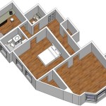
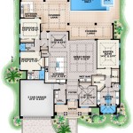
First Floor Plan Of Residence Detail Presented In This Autocad Drawing File 2d Auto Cad Layout Architecture

Residence Project Detail Specified In This Autocad Drawing File 2d Auto Cad Simple Floor Plans

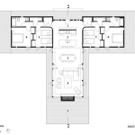
Modern Hospital Ground Floor Plan

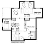
Autocad 2d Plan For Single Dwelling Unit Scientific Diagram

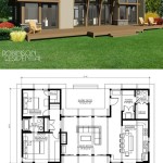
Architecraral 2d Plan Autocad Yahoo Image Search Results Interior Sketch Simple Floor Plans

Make 2d Floor Plan Over Autocad

Convert Blue Print To 2d Floor Plan Drawing At Rs 4 Square Feet In Bengaluru

Draw Any Type Of Autocad 2d Civil Drawings By Aanworks92 Fiverr

Draw Anythings Of Civil Buildings Plans In Autocad 2d By Mshoaib95 Fiverr

Hamadfach I Will Redraw 2d Floorplan Using Autocad With Very Fast Delivery For 5 On Fiverr Com Floor Plans Duplex Drawing House
Related Posts