Understanding Simple 2D Plan Drawing
Simple 2D plan drawing is a foundational skill in various fields, including architecture, engineering, interior design, and construction. It involves creating a two-dimensional representation of a space or object from a top-down perspective, accurately depicting its layout, dimensions, and key features. While modern technology offers sophisticated 3D modeling tools, the simplicity and clarity of 2D plans remain essential for initial design, communication, and efficient project management. Mastering the fundamentals of 2D plan drawing allows professionals to effectively communicate design ideas, analyze spatial relationships, and create accurate documentation for construction and fabrication.
The core principle of 2D plan drawing lies in representing the spatial reality onto a flat plane using specific conventions and symbols. This requires a systematic approach to capturing the essential elements of the space or object, prioritizing accuracy and clarity. The focus is on providing all necessary information for construction, renovation, or manufacturing, ensuring that the resulting product aligns with the intended design.
2D plans serve as the bridge between the conceptual design and its physical realization. They are used for obtaining permits, coordinating different trades involved in a project, and guiding construction activities. A well-executed 2D plan minimizes ambiguity, reduces errors, and ultimately contributes to the successful completion of a project. Therefore, understanding the elements and techniques involved in simple 2D plan drawing is crucial for anyone working in related industries.
Key Elements of a 2D Plan Drawing
A complete and effective 2D plan drawing consists of several essential elements that work together to convey all necessary information. These elements are typically standardized to ensure clarity and consistency across different projects and disciplines.
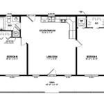
Walls and Partitions: Walls are represented as solid lines, typically thicker than other lines in the drawing to make them visually prominent. The thickness of the lines indicates the type of wall (e.g., load-bearing or non-load-bearing). Dimensions are included to specify the wall's length and thickness. Different hatching patterns or fill colors may be used to differentiate between various wall types, such as concrete, brick, or drywall.
Doors and Windows: Doors are represented by an arc indicating the swing direction and a line representing the door leaf. The opening size is specified with dimensions. Windows are typically represented by parallel lines with a gap in between, indicating the window frame and glazing. Window and door types are often indicated with callouts referencing a schedule that details the specific manufacturer, model, and specifications.
Furniture and Fixtures: Furniture, appliances, and other fixtures are represented using standardized symbols or representations that reflect their size and shape. These symbols are typically simplified versions of the actual objects to maintain clarity. For example, a sink may be represented by a circle or oval with a cross inside, while a toilet may be represented by a simple oval shape. Their placement within the plan indicates their intended location and arrangement within the space.
Dimensions and Annotations: Dimensions are crucial for specifying the precise size and location of all elements within the plan. They are typically displayed as lines with arrowheads pointing to the points being measured, along with the value of the measurement. Annotations are text labels used to identify specific objects, materials, or features. They provide additional information that may not be clear from the graphical representation alone.
Symbols and Legends: Symbols are used to represent various elements that are frequently used in drawings, such as electrical outlets, light fixtures, plumbing fixtures, and structural elements. A legend accompanies the plan, explaining the meaning of each symbol used. This ensures that everyone interpreting the plan understands the symbols and their corresponding representations.
Title Block: The title block is a standardized section of the drawing that contains essential information about the project, such as the project name, drawing title, drafter's name, date, scale, and revision number. This information is crucial for identifying and managing drawings throughout the project lifecycle.
The consistent use of these elements ensures that 2D plan drawings are easily understood and interpreted, regardless of who is viewing them. Accuracy and attention to detail in these elements are essential for creating effective and useful plans.
Essential Tools and Materials
While digital tools have largely replaced traditional methods, understanding the fundamentals of manual drafting remains valuable. A combination of traditional and digital tools is often used in practice, depending on the project requirements and individual preferences. Therefore, familiarity with both is advantageous.
Traditional Tools: Pencil, eraser, T-square, set squares (45° and 30/60°), compass, dividers, scales (architectural and engineering), drafting tape, and drafting paper or vellum are the basic tools for manual drafting. Each tool has a specific purpose and contributes to the accuracy and precision of the drawing.
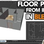
Digital Tools: Computer-Aided Design (CAD) software is the primary tool for creating 2D plan drawings digitally. Popular CAD software includes AutoCAD, Revit (though primarily a BIM tool, it can generate 2D plans), DraftSight, and LibreCAD. These software programs offer a wide range of features for creating, editing, and managing drawings, including layering, dimensioning, annotation, and plotting.
Specialized Software: Depending on the specific field, specialized software may be used to create 2D plans. For example, interior design software often includes libraries of furniture and fixture symbols, while electrical design software provides tools for creating electrical schematics and plans.
Printers and Plotters: Printers and plotters are used to produce hard copies of 2D plan drawings. Plotters are typically used for printing large-format drawings, such as architectural plans and engineering drawings. Choosing the right printer or plotter depends on the size and volume of drawings required.
The choice of tools and materials depends on the specific requirements of the project and the individual's skills and preferences. However, regardless of the specific tools used, accuracy and precision are paramount.
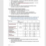
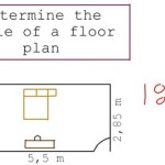
Importance of Scale and Accuracy
Scale and accuracy are fundamental to 2D plan drawing. The scale represents the ratio between the dimensions on the drawing and the actual dimensions of the object or space being represented. Accuracy ensures that the drawing accurately reflects the true dimensions and spatial relationships of the object or space.
Understanding Scale: Scale is typically expressed as a ratio, such as 1:100 or 1/4" = 1'-0". The first number in the ratio represents the unit of measurement on the drawing, while the second number represents the corresponding unit of measurement in reality. For example, a scale of 1:100 means that 1 unit on the drawing represents 100 units in reality. Common architectural scales include 1/8" = 1'-0", 1/4" = 1'-0", and 1/2" = 1'-0". The selection of an appropriate scale depends on the size of the object or space being represented and the level of detail required.
Ensuring Accuracy: Accuracy is achieved through careful measurement, precise drafting techniques, and the use of appropriate tools. When measuring the object or space, it is important to use accurate measuring devices and to double-check measurements to minimize errors. When drafting, it is important to use precise drafting techniques and to pay attention to detail. Digital tools can help to improve accuracy by providing precise dimensioning and editing capabilities. However, even with digital tools, it is important to verify the accuracy of the drawing.
Consequences of Inaccuracy: Inaccurate drawings can lead to significant problems, such as construction errors, fabrication mistakes, and spatial planning issues. These problems can result in costly rework, delays, and even safety hazards. Therefore, it is crucial to prioritize accuracy in all aspects of 2D plan drawing.
Scale and accuracy are essential for creating useful and reliable 2D plan drawings. By understanding the principles of scale and accuracy and by employing appropriate techniques and tools, professionals can ensure that their drawings accurately represent the intended design, leading to successful project outcomes.
In conclusion, while the process of creating simple 2D plan drawings may seem straightforward, the application of fundamental principles ensures the creation of accurate, readable, and valuable documents for a variety of professional purposes.

Create Professional 2d Floor Plans Roomsketcher

Draw 2d Floor Plans In Minutes Not Hours Cedreo

Create Professional 2d Floor Plans Roomsketcher

2d Drawing Gallery Floor Plans House

Beautiful 2d Floor Plan Ideas Engineering Discoveries Building House Plans Designs Simple Small

2d Floor Plans Plan Design Home Small Kitchen

Beautiful 2d Floor Plan Ideas Engineering Discoveries Home Map Design Building House Plans Designs

Create Professional 2d Floor Plans Roomsketcher

2d Floor Plan Archives Page 2 Of 6 Dk Home Designx

Create Professional 2d Floor Plans Roomsketcher
Related Posts