AutoCAD Floor Plans with Dimensions: A Comprehensive Guide
AutoCAD floor plans with dimensions are essential tools for architects, engineers, and designers to communicate design ideas and create accurate construction documents. They provide visual representations of building spaces, including walls, doors, windows, furniture, and other fixtures, along with precise measurements to ensure proper construction. This article will delve into the process of creating AutoCAD floor plans with dimensions, highlighting key considerations for accurate and effective plan generation.
1. Setting Up the Drawing Environment
Before drafting a floor plan, it's crucial to establish a solid foundation by properly configuring the AutoCAD environment. This includes defining drawing units, setting up layers and linetypes, and establishing a drawing scale.
-
Drawing Units:
Select appropriate units (e.g., millimeters, inches) based on the project's requirements. Consistent unit selection ensures accurate dimensioning and avoids confusion. -
Layers and Linetypes:
Create dedicated layers for different plan elements (e.g., walls, doors, furniture). Assign distinct linetypes to differentiate between walls, electrical lines, and plumbing lines, for easy visual identification. -
Drawing Scale:
Determine the scale for the floor plan, ensuring it represents the real-world dimensions accurately. A common scale for floor plans is 1:50, but the choice depends on the project's complexity and desired level of detail.
A well-organized drawing environment ensures a smooth drafting experience and maintains clarity throughout the plan development process.
2. Drafting Floor Plan Elements
Once the drawing environment is set up, focus on drafting the floor plan elements, which include walls, doors, windows, and other features. AutoCAD provides various tools specifically designed for this purpose.
-
Walls:
Utilize the "Wall" tool to create straight or curved walls. Define wall thickness, material, and other properties. Ensure smooth transitions at corners and intersections. -
Doors and Windows:
Insert pre-defined door and window blocks or create custom ones. Specify size, type, and placement according to architectural specifications. -
Furniture and Fixtures:
Find furniture and fixtures in AutoCAD's extensive library or create custom blocks to represent specific items. Place and arrange these elements to depict room layouts and functionality. -
Other Features:
Utilize appropriate tools for stairways, columns, beams, and other structural elements. Ensure accurate placement and dimensioning based on design plans.
As you draft elements, maintain consistency in line weights and styles to enhance visual clarity and prevent distortion in printed or digital outputs.
3. Adding Dimensions and Annotations
After drafting the floor plan elements, it's time to add dimensions and annotations to convey essential measurements and information. AutoCAD provides a comprehensive set of dimensioning tools to accurately communicate spatial relationships.
-
Linear Dimensions:
Measure distances between points using the "Linear Dimension" tool. Define dimension lines, arrows, and text to display the numerical values clearly. -
Radial and Angular Dimensions:
Measure radii, diameters, and angles using dedicated tools. -
Text and Leaders:
Utilize text commands to add notes, specifications, or labels. Leaders connect these text elements to the corresponding points on the plan. -
Dimension Styles:
Customize dimension styles to suit project requirements. Define line thickness, arrow styles, and text format, ensuring consistent display across the plan.
Pay close attention to dimensioning accuracy and avoid cluttering the plan with unnecessary or overlapping dimensions. Aim for a balanced display of critical measurements while maintaining visual appeal.
4. Enhancing the Floor Plan
To create a more comprehensive and informative floor plan, consider incorporating additional features beyond basic drafting and dimensioning. This includes adding layers for different design elements, using hatches and fills to highlight areas, and incorporating annotations for additional information.
-
Layers for Different Design Elements:
Create dedicated layers for electrical, mechanical, and plumbing systems to organize and isolate these elements visually. -
Hatches and Fills:
Use hatches to represent different materials like concrete, wood, or tile. Fills can be used to highlight specific areas like doorways, windows, or special flooring types. -
Annotations for Additional Information:
Include symbols, notes, and callouts. These can represent existing utilities, equipment locations, or specific design details that require additional clarification.
By incorporating these features, you can create a comprehensive floor plan that not only conveys the spatial layout but also provides essential information for construction and design decisions.

Making A Simple Floor Plan In Autocad Part 1 Of 3

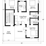
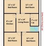
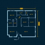
Ground Floor Plan In Autocad With Dimensions 38 48 House 35 50 Map 35x45 Plans How To

Basic Floor Plan Drafting In Autocad 7 Steps Instructables

Is Autocad The Best Floor Plan For Estate Agents Elements Property

How To Draw Floor Plans In Autocad Edrawmax

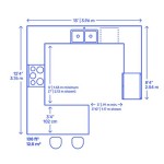
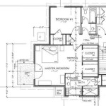
Autocad House Plans With Dimensions Bungalow Floor Plan

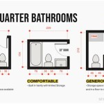
Autocad 2d Bathroom Floor Plans Graphic Design Courses

Solved Draw The Floor Plan In Autocad As Shown Chegg Com

Autocad Drawing And Coohom Design 3d Fast Rendering Blog

Autocad 2024 Floor Plan Tutorial
Related Posts