Making a Simple Floor Plan in AutoCAD: Part 2 of 3
This article, the second in a three-part series, delves into the specifics of creating walls, doors, and windows in AutoCAD after setting up the drawing environment, as discussed in Part 1. This stage is crucial in developing a functional and accurate floor plan representation.
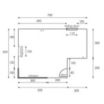
Creating Walls
Walls form the basic structure of any floor plan. AutoCAD offers several methods for creating walls, including the Line command for simple layouts and the Polyline command for more complex shapes. The Polyline command is generally preferred as it creates a single object representing the entire wall, simplifying edits and modifications. It also allows for varying wall thicknesses within the same object.
To draw a wall using the Polyline command, type “PLINE” in the command line and press Enter. Specify the starting point of the wall by clicking a point in the drawing area or entering coordinates. Continue clicking points to define the wall path, specifying wall length and direction. To change the wall thickness, enter “W” at the prompt and specify the desired width. Continue drawing the wall segments until the closed polygon representing the outer perimeter of the building is complete. Remember to close the polyline by typing “C” and pressing Enter or clicking the starting point.
Accurate representation of wall thickness is vital. This thickness should reflect the actual construction dimensions. Consistency in wall representation throughout the drawing maintains clarity and professionalism. Double-checking measurements ensures the drawn walls match the planned dimensions.
Inserting Doors and Windows
After establishing the walls, the next step involves inserting doors and windows. AutoCAD provides a robust library of pre-drawn blocks representing standard architectural elements. These blocks can be inserted directly into the drawing, saving time and ensuring consistent representation.
To access the standard blocks, type “INSERT” in the command line and press Enter. This opens the Insert dialog box. Navigate to the architectural library where doors and windows are typically located. Select the desired door or window block and click "OK." AutoCAD prompts for the insertion point. Click along the wall where the door or window should be placed. The block is inserted into the drawing. Ensure the doors and windows align correctly with the walls.
Customization of these pre-drawn blocks is also possible. Properties such as size, swing direction, and window type can be adjusted after insertion. This flexibility allows for precise representation of specific architectural designs. Explore the Properties palette to modify these attributes as needed. Consistent sizing and placement of doors and windows maintains a professional and readable floor plan.
Utilizing Layers for Organization
As the complexity of the floor plan increases, maintaining organization becomes paramount. AutoCAD’s layer functionality provides a crucial tool for managing different elements within the drawing. Layers act as transparent overlays, allowing users to group and control the visibility of specific objects. For example, walls, doors, windows, and dimensions can each be placed on separate layers.
Creating designated layers for different elements allows for selective visibility control. This can be useful when focusing on specific aspects of the design, such as electrical layouts or plumbing, without the visual clutter of other elements. By assigning specific colors and linetypes to each layer, visual distinction between different elements is enhanced, further improving the readability and clarity of the floor plan. Consistent use of layers is a hallmark of a well-organized and professional AutoCAD drawing.
By following these steps and incorporating the principles of accurate representation, consistent styling, and organized layers, a clear and informative floor plan can be developed in AutoCAD. Part 3 of this series will cover adding dimensions and text annotations to complete the floor plan.

Making A Simple Floor Plan In Autocad Part 2 Of 3

Autocad 2d Basics Tutorial To Draw A Simple Floor Plan Fast And Efective Part 1

Making A Simple Floor Plan In Autocad Part 3 Of

Autocad 2024 Making A Simple Floor Plan In Part 1 Of 3 2d Drawing

Making A Simple Floor Plan In Autocad Part 3 Of

How To Draw Floor Plans In Autocad Edrawmax

Autocad Tutorial Draw A House Floor Plan Free Cad Blocks In Dwg File Format

Basic Floor Plan Drafting In Autocad 7 Steps Instructables

How To Draw Floor Plans In Autocad Edrawmax

How To Draw Floor Plans In Autocad Edrawmax
Related Posts