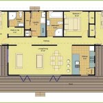
How To Draw a Simple Floor Plan in AutoCAD
Creating a simple floor plan in AutoCAD involves a systematic process using various drawing and editing tools. This article provides a step-by-step guide for developing a basic floor plan, focusing on fundamental techniques and best practices.
Setting up the Drawing
Accurate floor plans require proper initialization. This involves establishing units, limits, and layers for efficient organization.
- Units: Specify the desired units (e.g., architectural feet/inches or decimal). Access the UNITS command by typing UNITS in the command line.
- Limits: Set the drawing boundaries using the LIMITS command. This defines the workable area.
- Layers: Create layers for different elements (e.g., walls, doors, windows, dimensions). Layers facilitate organization and control visibility.
Drawing Walls
Walls form the primary structure of a floor plan. AutoCAD offers multiple methods for creating wall representations.
- Line Command: Use the LINE command (or the shortcut L) to draw individual wall segments. Specify start and endpoints by clicking or entering coordinates.
- Polyline Command: Create connected line segments with the POLYLINE (PL) command. This is useful for continuous wall sections.
- Rectangle Command: Draw rectangular rooms quickly using the RECTANG command (REC). Define two opposite corners to generate a rectangle.
- Offset Command: Create parallel lines to represent wall thickness. Use the OFFSET command (O) with the desired offset distance.
Adding Doors and Windows
Doors and windows are inserted into wall sections using specific commands and blocks.
- Insert Block: AutoCAD provides pre-drawn blocks for standard doors and windows. Access the INSERT command (I) to select and place these blocks.
- Create Your Own Blocks: Design custom door and window blocks using basic drawing commands and the BLOCK command (B) for future reuse.
- Positioning: Accurately place doors and windows within the wall lines, ensuring proper alignment and spacing.
Incorporating Other Architectural Features
Add essential elements such as stairs, fixtures, and appliances.
- Stairs: Utilize specific stair tools or create simplified representations using lines and polylines.
- Fixtures and Appliances: Insert blocks representing common fixtures like sinks, toilets, and appliances such as refrigerators and stoves.
- Furniture: Include furniture representations for a more complete floor plan visualization. Utilize pre-drawn blocks or create custom shapes.
Adding Dimensions
Clear and accurate dimensions are crucial for communicating the floor plan's measurements.
- Dimension Command: Use the DIM command to access various dimensioning tools (e.g., linear, aligned, angular).
- Dimension Styles: Customize dimension appearance (text size, arrowheads, units) through the Dimension Style Manager (DIMSTYLE).
- Accuracy: Ensure accurate placement of dimension lines and text for unambiguous interpretation.
Text and Labels
Adding text and labels helps clarify different areas and elements within the floor plan.
- Text Command: Use the TEXT (DT) command to insert text labels for room names, annotations, or other descriptive information.
- Text Styles: Control text appearance (font, size, style) through the Text Style dialog box (STYLE).
- Placement: Position text strategically for optimal readability and clarity.
Using Hatches and Fills
Hatches and fills provide visual distinction for different materials or areas.
- Hatch Command: Use the HATCH command to apply patterns within closed boundaries, representing different materials (e.g., tile, wood).
- Hatch Patterns: Select from a library of predefined hatch patterns or create custom patterns.
- Solid Fills: Use solid fills to represent areas with uniform materials.
Layout and Presentation
Finally, prepare the floor plan for printing or presentation.
- Layout Tabs: Create layouts within AutoCAD to specify paper size, orientation, and scale.
- Viewports: Utilize viewports within the layout to display specific portions of the floor plan at desired scales.
- Title Block: Add a title block containing project information, drawing scale, and other relevant details.

How To Draw Floor Plans In Autocad Edrawmax

Making A Simple Floor Plan In Autocad Part 2 Of 3

How To Draw Floor Plans In Autocad Edrawmax

How To Draw Autocad Floor Plan Cad Cam Blog

Making A Simple Floor Plan In Autocad Fantasticeng

Autocad 2d Basics Tutorial To Draw A Simple Floor Plan Fast And Effective Part 2

Autocad Simple Floor Plan For Beginners 1 Of 5

How To Make House Floor Plan In Autocad Fantasticeng

Autocad Tutorial Draw A House Floor Plan Free Cad Blocks In Dwg File Format

How To Draw Floor Plans In Autocad Edrawmax
Related Posts

