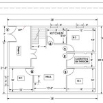
Essential Aspects of Typical Scale For Site Plan Drawings
Site plan drawings are crucial for visualizing and planning the layout of a construction project. Choosing the appropriate scale is essential for ensuring that the drawing accurately represents the site's dimensions and features.
Why Scale Matters
The scale of a site plan drawing determines the ratio between the drawing's dimensions and the actual dimensions of the site. A well-chosen scale allows for clear and legible representation of all relevant details, including buildings, roads, utilities, and landscaping.
Common Scales
The most commonly used scales for site plan drawings include:
*- 1:50
- 1:100
- 1:200
- 1:500
- 1:1000
These scales provide a range of detail levels, with smaller scales suitable for large-scale projects and larger scales for smaller, more detailed areas.
Factors to Consider
When selecting a scale for a site plan drawing, several factors should be considered:
*- Site size: Smaller sites require larger scales to display all necessary details, while larger sites can accommodate smaller scales.
- Level of Detail: More detailed drawings require larger scales to ensure clarity.
- Intended Use: The purpose of the drawing (e.g., planning, permitting, construction) influences the appropriate scale.
Example
For a site plan drawing of a residential property with a lot size of 100 feet by 150 feet, a scale of 1:100 would be appropriate. This scale provides a balance between detail and overall view, allowing for clear representation of the house, driveway, landscaping, and other features.
Conclusion
Choosing the correct scale for a site plan drawing is crucial for effective design and communication. By considering site size, level of detail, and intended use, engineers and architects can ensure that their drawings convey accurate and comprehensive information.

Site Plan Designing Buildings

A Typical Site Plan Scientific Diagram

Site Plan Wikipedia

How To Measure Distances In Technical Drawings With Custom Scale Annotator

07 02 Calculating Scale When Your Plan Does Not Include Or The Is Incorrect Constructconnect Help

Scale On Drawings Structural Engineering General Discussion Eng Tips

How To Draw A Floor Plan Scale Measuring Sketching

Site Plans What They Are And How To Create One

How To Draw A Floor Plan Scale Measuring Sketching

Site Plans What They Are And How To Create One
Related Posts

