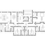
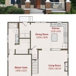
Simple House Floor Plan AutoCAD with Dimensions in Meters and Feet
Creating a clear and accurate floor plan is the first step in any successful building project. AutoCAD, a powerful computer-aided design (CAD) software, provides the necessary tools to draft precise and detailed floor plans. This article will guide users through creating a simple house floor plan in AutoCAD, incorporating dimensions in both meters and feet.
Setting Up the Drawing
Begin by setting up the drawing environment in AutoCAD. This includes defining the units of measurement and creating the necessary layers for different elements of the floor plan.
- Launch AutoCAD and select a new drawing template. Choose a template with metric or imperial units, depending on the primary unit system desired.
- Type "UNITS" in the command line and press "Enter." In the Drawing Units dialog box, choose "Decimal" for the unit type, and set "Precision" to two decimal places.Select "Meters" or "Feet" as the primary unit.
- Create layers for different components of the floor plan like walls, doors, windows, and dimensions. Use descriptive layer names (e.g., "A-WALL," "A-DOOR," "A-WINDOW," "A-DIM"). Assign appropriate colors and linetypes to each layer for better visualization.
Drawing the Walls
With the setup complete, the next step is to draw the exterior and interior walls of the house. Accuracy is crucial at this stage to ensure the correct representation of the house's layout.
- Select the "Wall" layer.
- Use the "Line" command (or "Polyline" for continuous wall segments) to draw the outer perimeter of the house. Input the wall lengths in the chosen unit system (meters or feet).
- Draw the interior walls, dividing the space into rooms according to the desired floor plan.
- Specify the wall thickness by offsetting the lines. The offset distance represents the wall's width.
Adding Doors and Windows
Once the walls are in place, doors and windows can be inserted into the drawing. AutoCAD offers pre-built blocks for standard door and window sizes, streamlining this process.
- Select the appropriate layer ("A-DOOR" or "A-WINDOW").
- If using pre-built blocks, insert them into the drawing and position them within the wall openings.
- Alternatively, draw rectangles representing the doors and windows using the "Rectangle" command. Adjust the dimensions to match the desired sizes.
- Add a swing arc to indicate the door's opening direction.
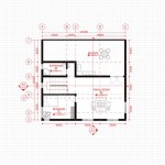
Applying Dimensions
Accurate dimensioning is vital for conveying the size and scale of the floor plan. This process involves adding linear, aligned, and angular dimensions to clarify the drawing.
- Select the "A-DIM" layer.
- Use the "Linear Dimension" command to add dimensions to walls, indicating their lengths and widths.
- Use the "Aligned Dimension" command for angled walls or features.
- Utilize the "Angular Dimension" command to show the angle between walls or other elements.
- For dual dimensioning (meters and feet), type “DIMASSOC” in the command line and set the value to “2”.
- Ensure the dimension style is set to display both primary and secondary units. This allows for simultaneous display of dimensions in both meters and feet.
Adding Text and Labels
Clear labels and annotations enhance the readability of the floor plan. Adding room names and other relevant information can be done with the text tools in AutoCAD.
- Select the appropriate layer for text (e.g., "A-TEXT").
- Utilize the "Text" command to add room names and labels. Choose a clear and legible font.
- Adjust the text size and position for optimal readability.
Adding Furniture and Fixtures
While not always essential for a basic floor plan, adding furniture and fixtures can provide a better visualization of the space.
- Create a new layer for furniture (e.g., "A-FURN").
- Utilize pre-built blocks for standard furniture items, or draw simple shapes to represent furniture pieces.
- Scale the furniture to match the real-world dimensions.
Saving and Exporting the Drawing
Once the floor plan is complete, save the drawing in the native AutoCAD DWG format for future edits. Exporting to other formats like PDF makes sharing and printing more convenient.
- Save the drawing as a DWG file.
- Export the drawing as a PDF for sharing or printing. Ensure the chosen scale preserves the accuracy of the dimensions.
By following these steps, users can effectively create simple yet accurate house floor plans in AutoCAD, incorporating dimensions in both meters and feet. The utilization of layers, precise dimensioning, and clear labeling ensures a professional and easily understandable drawing that serves as a solid foundation for any building project.

2d Floor Plan In Autocad With Dimensions 38 X 48 Dwg And File Free

Making A Simple Floor Plan In Autocad Part 1 Of 3

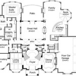
Autocad House Plans With Dimensions

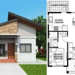
Simple Small House Design 7x6 Meter 23x20 Feet Pro Home Decors

12 Examples Of Floor Plans With Dimensions

2d Floor Plan In Autocad With Dimensions 38 X 48 Dwg And File Free

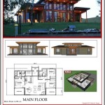
Simple House Design 10x8 Meter 27x34 Feet Pro Home Decors

1600 Square Feet House Floor Plan Cad Drawing Dwg File Cadbull

Autocad House Plan Plot Area 100 Sq M Fantasticeng

Floor Plan Free Cads
Related Posts