Dimensions In Plan: A Comprehensive Guide to Essential Aspects
Dimensions In Plan (DIP) is a critical component of architectural and engineering drawings, providing precise measurements and proportions for the design and construction of buildings and structures. Understanding the essential aspects of DIP is crucial for accurate execution of construction projects and ensuring the intended functionality and aesthetics of any built environment.
1. Accuracy and Precision
DIP requires meticulous attention to accuracy and precision. Measurements should be taken with appropriate tools and calibrated equipment to ensure consistency and prevent errors. Even small deviations from the intended dimensions can lead to costly rework or compromise structural integrity.
2. Projected and Plan Views
DIP involves creating both projected and plan views of a structure. Projected views depict the object from the side or front elevation, while plan views provide a bird's-eye perspective. These views are essential for capturing the exact dimensions, proportions, and relationships between different elements.
3. Scale and Units
The scale of DIP is crucial for accurate interpretation and execution. The selected scale should allow for clear and legible measurements without overcrowding or exceeding the size of the drawing. Common scales include 1/4 inch = 1 foot, 1/2 inch = 1 foot, and 1 inch = 1 foot.
4. Dimension Lines and Arrows
Dimension lines are used to indicate the distance between two points. They are typically drawn with a solid or dashed line and should extend slightly beyond the relevant elements. Dimension arrows are placed at the ends of dimension lines to indicate the direction of measurement.
5. Dimension Text
Dimension text should be clear and easy to read. It can be written horizontally or vertically and should include the appropriate unit of measurement. The text should be placed outside the dimension line, aligned with the center of the line.
6. Witness Lines
Witness lines are short lines that connect the dimension lines to the relevant elements. They ensure that the measurement is associated with the correct points and prevents ambiguity.
7. Dimensioning Conventions
There are various dimensioning conventions that have been established to maintain consistency and clarity in DIP. These conventions include the use of different line weights for different types of dimensions, the placement of dimensions outside the object being dimensioned, and the avoidance of dimension lines crossing each other.
Conclusion
Dimensions In Plan are an essential aspect of architectural and engineering drawings, providing critical information for accurate construction and the realization of design intent. By adhering to the principles of accuracy, precision, scale, and established conventions, professionals can create comprehensive and reliable DIP that facilitate efficient execution of construction projects and ensure the integrity and aesthetics of the built environment.

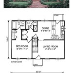
12 Examples Of Floor Plans With Dimensions

How To Read A Floor Plan With Dimensions Houseplans Blog Com

12 Examples Of Floor Plans With Dimensions

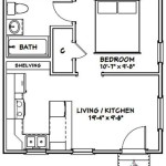
Floor Plans With Dimensions Including Examples Cedreo

Adding Dimensions To Your Floor Plan

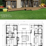
12 Examples Of Floor Plans With Dimensions

Floor Plans With Dimensions Including Examples Cedreo

Floor Plan With Dimensions Guide To Drawings

How To Read Floor Plans

Plans Simple Floor Measurements Jhmrad 611
Related Posts