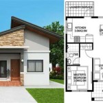
Typical Scales Used for Floor Plans
Floor plans are fundamental architectural drawings that depict the arrangement of spaces within a building as viewed from above. These plans serve as blueprints for construction, renovation, and interior design, and their accuracy hinges on the scale to which they are drawn. The scale of a floor plan represents the relationship between the dimensions on the drawing and the corresponding dimensions in the real world. Choosing the appropriate scale is crucial for legibility, representation of detail, and overall usability of the plan by architects, engineers, contractors, and homeowners.
The selection of a suitable scale for a floor plan depends on several factors, including the size of the building, the complexity of the design, the level of detail required, and the intended purpose of the plan. Different scales offer varying levels of precision and are better suited for specific applications. Consequently, understanding the common scales used and their implications is essential for anyone involved in the building design and construction process. This article will explore the typical scales employed in floor plan creation, highlighting their advantages and disadvantages and illustrating how different scales can be used effectively to represent various types of buildings and features.
Understanding Scale Representation
Architectural scales are typically expressed as a ratio or a fraction. This ratio indicates how much smaller the drawing is compared to the actual building. For example, a scale of 1:100 (or equivalently, 1/100) means that one unit of measurement on the drawing (e.g., one centimeter or one inch) represents 100 of the same units in reality. This ratio can apply to any unit of measurement, as long as the units on both sides are consistent. Therefore, 1 inch on the drawing represents 100 inches in reality, and 1 centimeter on the drawing represents 100 centimeters in reality.
In the United States, architectural scales are often expressed using imperial units, such as inches and feet. A common scale is ¼" = 1'-0" (quarter inch equals one foot). This means that one quarter of an inch on the drawing represents one foot in the real world. Similarly, ½" = 1'-0" represents half an inch on the drawing equaling one foot in the actual building. These scales are frequently found in residential construction plans.
For international designs or projects adhering to metric standards, scales are expressed in metric units (millimeters, centimeters, and meters). For instance, a scale of 1:50 indicates that 1 unit (say, a millimeter) on the plan corresponds to 50 units (millimeters) in the actual building. Similarly, 1:100 indicates 1 millimeter on the plan represents 100 millimeters in reality, which is equivalent to 10 centimeters. Accuracy in scale representation is vital, as any misinterpretation can lead to mistakes in the construction process.
It is crucial to note that the chosen scale directly affects the amount of detail that can be clearly depicted on the plan. A larger scale (e.g., 1:20 or ½" = 1'-0") allows for finer details to be shown, such as the thickness of walls, placement of fixtures, and smaller architectural elements. A smaller scale (e.g., 1:200 or 1/8" = 1'-0"), conversely, necessitates a simpler representation, sacrificing detail for the sake of overall layout and proportions of the building. The appropriate scale selection must therefore align with the plan's purpose and the required level of detail.
Common Scales and Their Applications
Several scales are frequently used in architectural drawings, each serving a specific purpose. The choice depends on the type of building, the level of detail required, and the intended use of the floor plan. The following are some of the most common scales and their general applications:
1:50 (or ¼" = 1'-0" or ½" = 1'-0" in imperial units): This is a commonly used scale for detailed residential floor plans. It is large enough to show the thickness of walls, door swings, window details, and the placement of furniture and fixtures. This scale provides a good balance between showing detail and maintaining a manageable drawing size for typical residential buildings. Its popularity stems from its ability to accommodate most necessary information while remaining relatively easy to read and interpret.
1:100 (or ⅛" = 1'-0" or 3/16" = 1'-0" in imperial units): This scale is often employed for slightly larger residential projects or smaller commercial buildings. It allows for the representation of room layouts, door and window placements, and basic structural elements. While less detailed than 1:50, it remains suitable for communicating the essential spatial relationships within a building. Often used in preliminary design phases or for schematic drawings when overall layout is the primary focus.
1:200 (or 1/16" = 1'-0" in imperial units): This scale is typically used for larger buildings, such as schools, office buildings, or apartment complexes. It allows architects to show the overall layout of the building, including the location of walls, corridors, and major spaces. At this scale, individual details are generally simplified or omitted to avoid overcrowding the drawing. This scale is suitable for showing the overall spatial organization but not for representing intricate details.
1:500 (or 1/32" = 1'-0" in imperial units): This scale is primarily used for site plans or very large buildings where the focus is on the building's relationship to its surroundings. Individual rooms and internal details are not typically shown at this scale. The emphasis is on the overall building footprint, access points, landscaping, and the relationship to neighboring structures. This is the scale of choice for conceptual layouts or preliminary site analyses.
Larger Scales (e.g., 1:20 or 1" = 1'-0" in imperial units): These are used for specific details, such as bathroom layouts, kitchen designs, or millwork details. These drawings require a higher level of precision and clarity, allowing for the detailed representation of fixtures, materials, and construction methods. Such enlarged plans are often used in conjunction with smaller-scale overall floor plans to provide a comprehensive understanding of the building.
Factors Influencing Scale Selection
Beyond the type and size of the building, several other factors can influence the selection of an appropriate scale for a floor plan. These considerations include the plan's purpose, the target audience, and the available drawing space.
Purpose of the Plan: If the plan is intended for obtaining building permits, it will likely require a higher level of detail and therefore a larger scale. This ensures that all necessary information, such as wall dimensions, fire ratings, and accessibility features, are clearly represented. Conversely, a floor plan used for preliminary design presentations might prioritize overall spatial arrangements over minute details, allowing for the use of a smaller scale.
Target Audience: The intended audience for the floor plan can also impact the scale choice. For instance, a homeowner might benefit from a detailed plan at a larger scale (e.g., 1:50) that clearly shows furniture placement and fixture locations. On the other hand, a contractor primarily concerned with structural elements might find a plan at 1:100 or 1:200 more suitable, as it emphasizes the overall building layout and dimensions without overwhelming them with unnecessary detail.
Drawing Size and Legibility: The physical or digital size of the drawing sheet is a critical factor. A very large building drawn at a large scale might exceed the available drawing space, necessitating a smaller scale to fit the entire plan onto a single sheet. Similarly, if the drawing becomes too crowded with details, it can become illegible and difficult to interpret, even if a larger scale is used. A balance must be struck between representing sufficient detail and maintaining clarity. Computer-aided design (CAD) software allows for flexible scaling and printing, but even digital drawings should adhere to legibility principles.
Regulatory Requirements: Local building codes and regulations may specify minimum scale requirements for certain types of drawings. These requirements ensure that the plans submitted for review are sufficiently detailed to allow for accurate assessment of compliance with safety and accessibility standards. Architects and designers must be aware of these requirements and choose a scale that meets or exceeds the minimum standards.
Ultimately, selecting the appropriate scale for a floor plan is a balance between representing the required level of detail, maintaining legibility, and accommodating the physical constraints of the drawing. Understanding the various common scales and their applications allows architects, designers, and contractors to effectively communicate the intended design and ensure the successful execution of the building project.

In Reviewing An Architectural Drawing Representing A Floor Plan Of Certain Building How Does One Determine The Locations Each Pad Footing That Area Quora

How To Properly Read Floor Plans And What Details Look For

How To Read A Basic Floor Plan Lofty Building Group

How To Read A Floor Plan With Dimensions Houseplans Blog Com

12 Examples Of Floor Plans With Dimensions

Floor Plan Wikipedia

How To Measure And Draw A Floor Plan Scale

How To Read Floor Plans With Dimensions A Guide

Floor Plans With Dimensions Including Examples Cedreo

Do You Know How To Read Floor Plans
Related Posts