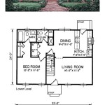
Understanding 2D Plan Drawings with Dimensions
2D plan drawings, fundamental to architecture, engineering, and construction, serve as graphical representations of a structure or space viewed from above. These drawings distill complex three-dimensional realities into comprehensible two-dimensional formats, providing essential information for planning, design, and execution. A crucial aspect of these drawings lies in their accurate and detailed dimensions, which dictate the size, shape, and relative positioning of various elements within the plan. Without precise dimensions, the drawing loses its practical value and becomes a mere aesthetic representation, prone to misinterpretation and construction errors.
This article will explore the key elements and significance of 2D plan drawings, with a specific focus on understanding dimensions and their role in translating design concepts into tangible structures. We will examine the different types of dimensions commonly used, the conventions followed in their representation, and the importance of accuracy in ensuring successful project outcomes. A thorough understanding of these principles is essential for anyone involved in the building process, from architects and engineers to contractors and clients.
Key Point 1: Types of Dimensions and Their Representation
Dimensional information on 2D plan drawings is conveyed through a standardized system that includes various types of dimensions, each serving a specific purpose. Understanding these types and their correct representation is crucial for interpreting the drawing accurately.
Overall Dimensions: These dimensions indicate the total length and width of the structure or space being represented. They typically encompass the entire outer boundary of the plan and provide a general understanding of the building's footprint. Overall dimensions are usually placed prominently on the drawing, often using heavier line weights to emphasize their significance. They are critical for site planning, determining building setbacks, and ensuring compliance with zoning regulations.
Intermediate Dimensions: These dimensions break down the overall dimensions into smaller segments, specifying the distances between key structural elements such as walls, columns, and partitions. They provide a more detailed understanding of the layout and arrangement of interior spaces. Intermediate dimensions are essential for accurately positioning interior walls, doors, and windows, and for ensuring that rooms and spaces meet their intended size requirements.
Detailed Dimensions: These dimensions focus on specific features or elements within the plan, providing highly precise measurements for their size, shape, and location. Examples include the width of a door opening, the thickness of a wall, or the diameter of a column. Detailed dimensions are crucial for ensuring that individual components are fabricated and installed correctly. They are particularly important for intricate details that require precise alignment or fitting.
Coordinate Dimensions: In some cases, coordinate dimensions are used to specify the location of points or features relative to a fixed origin point. This system uses X and Y coordinates to define the position of elements, providing a highly accurate and unambiguous method of specifying their location. Coordinate dimensions are often used in conjunction with Computer-Aided Design (CAD) software and are particularly useful for complex geometries or irregular shapes.
Dimension Lines and Extension Lines: Dimensions are indicated visually using dimension lines, which are thin, continuous lines that run parallel to the feature being dimensioned. Extension lines, also known as witness lines, extend from the feature to the dimension line, indicating the points between which the dimension applies. The dimension value, representing the measured distance, is typically placed above the dimension line, either horizontally or aligned with the line. Arrowheads are placed at the ends of the dimension line, pointing towards the extension lines to clearly indicate the extent of the dimension.
Symbols and Abbreviations: Standard symbols and abbreviations are used to represent various units of measurement (e.g., feet, inches, meters, millimeters) and specific features (e.g., diameter, radius). The use of these conventions ensures consistency and clarity in the drawing, reducing the potential for misinterpretation. A legend or key is often included with the drawing to define the symbols and abbreviations used.
Key Point 2: Conventions and Standards in Dimensioning
Adherence to industry-standard conventions and best practices in dimensioning is paramount for creating clear, accurate, and unambiguous 2D plan drawings. These conventions ensure that the drawing can be easily understood and interpreted by all stakeholders involved in the project. Several key aspects of dimensioning conventions deserve attention.
Placement of Dimensions: Dimensions should be placed outside the object or feature being dimensioned whenever possible, to avoid cluttering the drawing and obscuring important details. Dimensions should also be staggered to prevent overlapping and improve readability. It is generally recommended to place smaller dimensions closer to the object and larger dimensions further away. Consistent placement helps the reader quickly locate and interpret the dimensional information.
Units of Measurement: The units of measurement used in the drawing should be clearly indicated, typically in the title block or a separate note. Commonly used units include feet and inches (imperial system) or meters and millimeters (metric system). Consistency in the use of units throughout the drawing is essential to avoid errors and confusion. If different units are used for specific features, this should be clearly noted.
Accuracy and Precision: Dimensions should be accurate and reflect the intended size and shape of the features being represented. The level of precision required depends on the nature of the project and the tolerance requirements of the individual components. For example, structural elements may require a higher degree of precision than non-structural finishes. Rounding dimensions should be done carefully and consistently, ensuring that the overall accuracy of the drawing is maintained.
Avoidance of Redundancy: Dimensions should be provided only once for each feature or element, avoiding unnecessary duplication or redundancy. Redundant dimensions can lead to confusion and potentially conflicting information. If a feature is dimensioned in one view, it should not be dimensioned again in another view unless there is a specific reason for doing so.
Clarity and Readability: Dimensions should be clear and easy to read, with appropriate line weights, text sizes, and spacing. Overlapping lines and text should be avoided, and the drawing should be free of unnecessary clutter. The overall presentation of the drawing should be professional and visually appealing. Clear and readable dimensions contribute significantly to the accuracy and efficiency of the construction process.
Use of Notes: Notes should be used to provide additional information or clarification about specific dimensions or features. Notes can be used to specify tolerances, material requirements, or any other relevant information that is not readily apparent from the drawing itself. Notes should be placed close to the feature or dimension they refer to and should be clearly labeled.
Key Point 3: The Importance of Accuracy and Its Impact
Accuracy in 2D plan drawings, particularly in the representation of dimensions, is critical for the success of any construction project. Errors in dimensions can lead to a cascade of problems, ranging from minor inconveniences to significant delays and cost overruns. The impact of inaccurate dimensions can be far-reaching and affect all stages of the construction process.
Fabrication and Manufacturing Errors: Inaccurate dimensions can result in the fabrication or manufacturing of components that do not fit together properly. This can lead to delays in the construction schedule, as components need to be reworked or replaced. It can also result in increased costs, as additional materials and labor are required to correct the errors. In extreme cases, inaccurate dimensions can compromise the structural integrity of the building.
Site Layout and Positioning Issues: Inaccurate overall dimensions can lead to errors in site layout and positioning. The building may be placed in the wrong location on the site, or it may not meet the required setbacks from property lines. This can result in legal issues and costly rework. Accurate dimensions are essential for ensuring that the building is properly positioned and aligned with the surrounding environment.
Coordination Problems: Inaccurate dimensions can create coordination problems between different trades and subcontractors. For example, if the dimensions of a room are incorrect, the flooring contractor may order the wrong amount of material, or the electrical contractor may install the wiring in the wrong location. These coordination problems can lead to delays, conflicts, and increased costs. Accurate dimensions are essential for ensuring that all trades and subcontractors are working from the same information.
Cost Overruns: The cumulative effect of errors caused by inaccurate dimensions can result in significant cost overruns. Rework, delays, and coordination problems all contribute to increased costs. In some cases, the cost of correcting errors can exceed the initial budget for the project. Accurate dimensions are essential for minimizing the risk of cost overruns and ensuring that the project stays within budget.
Legal Liability: Inaccurate dimensions can create legal liability for the architect, engineer, or contractor responsible for the drawing. If errors in the drawing result in damages or injuries, the responsible party may be held liable. Accurate dimensions are essential for protecting against legal claims and minimizing the risk of liability.
Communication Issues: Inaccurate or unclear dimensions can lead to miscommunication between the various stakeholders involved in the project. If the drawing is difficult to understand or interpret, it can lead to misunderstandings and errors. Clear, accurate, and unambiguous dimensions are essential for effective communication and collaboration.
The creation and interpretation of 2D plan drawings with accurate dimensions are fundamental skills for professionals in the architectural, engineering, and construction industries. A solid understanding of dimensional types, conventions, and the potential consequences of inaccuracies contributes directly to project success, cost efficiency, and overall safety. Continuous professional development and adherence to industry best practices are encouraged to maintain proficiency in this critical area.

Draw 2d Floor Plans In Minutes Not Hours Cedreo

Create Professional 2d Floor Plans Roomsketcher

2d Floor Plan Archives Page 2 Of 6 Dk Home Designx

Create Professional 2d Floor Plans Roomsketcher

Beautiful 2d Floor Plan Ideas Engineering Discoveries Home Map Design Building House Plans Designs

Detailed 2d Drawings For Interior Architecture Design

2d Floor Plan Design At Rs 5 Square Feet In Raigad Id 22492210473

2d Drawing Gallery Floor Plans House

2d Plan Of The Existing First Floor Building All Dimensions Are In M Scientific Diagram

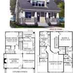
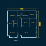
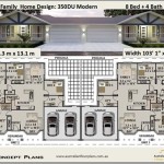
12 Examples Of Floor Plans With Dimensions
Related Posts